Jump to content
  • Join our community

    Sign-up for free and join our friendly community to chat and share all things R/C!

It's project time!


Nitroholic

Recommended Posts

That's the intention. I got a selection of shocks to play with varying from buggy shocks through to some ~Savage extra long jobbies.


I have to play with the shock mounts and the angles to get the droop when unloaded whilst still being able to keep the back end off the deck!

Link to comment
Share on other sites

its not the shocks, its the internals. 


that chap is running the RPM floating pistons. 


they are two piston plates, where usual shocks have one piston plate 

the pistons are two plates, the lower plate has say 4 holes in it, and the upper plate has 8 holes.

as the shock is compressed both the upper and lower plates squash together this means only oil can flow through four holes.

when the shock decompresses the pistons drag open and allow eight holes to be opened for oil flow, as well as the four lower holes.

hence your rebound is very very fast like in the video. 


only problem is the shock pistons are for 1/10th size shocks only , and do not fit bigbore shocks


Surely that just needs a second floating piston. If I cut a thread on the upper end of the shock shaft, I can thread on the lower piston and then just hold the top piston on with a nut. The lower piston has to be fixed with the larger holes.....and the upper piston slides with fewer holes.

Link to comment
Share on other sites

Surely that just needs a second floating piston. If I cut a thread on the upper end of the shock shaft, I can thread on the lower piston and then just hold the top piston on with a nut. The lower piston has to be fixed with the larger holes.....and the upper piston slides with fewer holes.


somewhat buddy  if you look at the picture below you can see they are two plates but they still joint together

one plate has a raised inner ring and this fits into a upper larger ring. with a e-clip ontop the upper plate is allowed to over up anddown freeley

but the lower plate stays fixed. 


i think the cnc boys could knock a few bigbore types up. 


acf937cb5fb37e09bb494626955f22e0.jpg


and how it is put together via rpmwebsite


pistons2.gif

Edited by Tamiyacowboy
Link to comment
Share on other sites

Another option for a faster stage at the in the damper is to machine a small groove or two in the inside wall of the shock cylinder for the section you want less damping.  The groove acts as a bypass.  I've always thought it would be hard to get a consistent result though at RC scale.  MIP do a tunable bound / rebound set of pistons too (weird hex shape).  I think 1:1 have partly damped bump stops for the really big hits and limiting straps for big jumps.

Link to comment
Share on other sites

I have a few ideas to play about with on this.


I could achieve a similar effect with a reed valve type assembly. Have an 8 hole piston in the normal place, and then put a cross shaped piece of thin lexan on top, all held down by the stock c-clip. On extension, the 4 arms of the cross would flex, allowing the damper to move easily and oil to flow up through the piston. Then...on compression, the oil would force the lexan down onto the piston, reducing the flow of oil downwards. Simpler to make and easy to test.


I have also considered using double springs. A shorter one outside a longer one. Fixed on the upper end. Then, you have a 2 stage compression allowing the use of a softer spring for the first part of the travel, but if the damping does the trick....I won;t need that. I am also looking at rising rate linkages to stiffen up the last part of the travel to keep the tail from dragging

Link to comment
Share on other sites

  • 3 weeks later...

Been a couple of weeks, and not much progress. PayPal has decided I can;t put money in...and a few silly bits and pieces took ages to get to me....but things are back on track now.


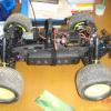
Chassis is now metal, and I am getting the steering setup and the front brace. The alloy chassis is wider than the wooden mockup, as I have taken it the full width of the shell. I will put some thin-ish ally angle bracket down each side with some rubber/foam on to act as buffers and to support the shell.


Next big job is to make up the proper 4 link back end. I have some Delrin sheet and finally have a 24mm drill bit to bore out the holes where the brackets go over the axle. The main swing axles will be composites. Outer skin ally sheet....inner blocks Delrin, so I can screw the rod ends in easy.


Got a bit of tidying up to do, then I can post some more pictures

Link to comment
Share on other sites

Been too hot to do much, but managed to get cracking and make some progress this weekend. Ok...well actually I've been messing about with the Savage XS...but hey :)


With the ally chassis in place, the steering posts could be located and screwed in. I will be making a custom upper brace, but that will come later after I have the motor mounts done. Current plan is to use a set of Hyper 9 angled mounts as soon as PayPal stops being stupid and lets me upload funds!


dt1_zpsfge9dezb.jpg


The rear axle mountings have been finalised in mock up, and the real ones have been done. I needed to wait on delivery of a 24mm drillbit to mach the exact diameter of the axle tube. The outer mounts for the main arms slot over the tube and are bolted up to a pair of the shock mounts. This stops it twisting and gives a rigid mount. There was a slight gap so an ally shim was made up to remove any slop.


dt2_zpsgicji1kb.jpg


A similar block makes up the inner mounting. This one is slotted at the back to allow it to clamp, and then a pair of long bolts go through and bolt onto the upper plate to make it nice and tight. The rear wheel tie rods had to go, so a simple angle bracket now does that job. The main arms are delrin with 5mm tie rod ends at each end. I plan to fit an ally outer layer for looks and support. The upper arms are similar tie rods...but I need to find some different ones, as these have limited angles of movement compared to the lower ones.


dt3_zpsjuvauabf.jpg


Next job is to finish off the other side and fit hte angle brackets for the arm mounts. I need to have the lower arms in line with the diff cup to keep the driveshaft in place, but I can get the angles I want. Savage shocks have been tested and look to be the best option. Gives me the choice of a pair ( with one spring off ) or a single... provides travel and droop.


Pretty happy with how it's going so far.

  • Like 1
Link to comment
Share on other sites

Just noticed one slight hitch looking at the pics. I have drilled the holes for the upper links symetrical on the plate....but the diff is not central. I cut the tubes equally, and the diff is slightly offset as standard. The upper link holes need to be further over to the right. The plate is wide enough ( I avoided a 'shark-fin' fiting to leave room for this ) but I need to remember to do this or the top links will be odd lengths!


Next job is to cut the angle brackets to support the suspension links and get those fitted.


I also need to fabricate the suspension tower at the back and work out the spare wheel mounts. I also have a couple of old Hyper shells which I intend to slice up and make inner wings/mudguards to keep the muck under control and keep the wheels from grinding the paint off the shell. I also plan on cutting out the rear centre section of the shell and making a rollcage..... just haven't worked out hte details there yet :)

Link to comment
Share on other sites

Quick question for all you crawler types....


I have a limit in terms of suspension travel, as when you go too far...the driveshaft binds in the cup, and this is 'bad'.


I have made up a set of top links for the 4 link suspension, but I think I need to make them slightly longer. Am I right in thinking that a longer top link will angle the rear diff input  up and allow more droop before it hits the bind point? The suspension can travel far further up than I need, as the shell is the limit point there.


Have used some different ball joints on the upper links and got a decent degree of flex....just as it stands, I have enough droop to drop the wheels so the top of the tyre is about level with the chassis plate line....which is about what I want ... but at this point the rear wheels lock and the driveshaft touches the edge of the drive cup.


Want to sacrifice some upward movement for some free downward movement :)


Anyways...have the rear suspension all fitted up, the driveshaft does not drop out and I have plenty of articulation. Shock towers are next. Then I need to make up the rear cage and spare tyre mounts

Link to comment
Share on other sites

Longer up links will adjust the diff. output angle as you say but not sure how it'll behave with a dogbone as the angle will change with articulation. You might need to adjust the chassis mounting points to compensate. Crawlers usually have a sliding driveshaft for this reason.

4 link suspension is tricky and makes my head hurt if I think about all the possibilities too much!

Sent from my HTC One X+ using Tapatalk

Link to comment
Share on other sites

Cheers :)


confirmed what I was thinking. The driveshaft is fine in terms of length and the level of articulation in the finished object isn;t as much as a crawler. I have made sure the lower link pivots are exactly level with the 'pivot' point of the driveshaft at the front, so driveshaft lengths vary...but within the tolerances of the drive pins.


Crawlers don;t do that, as it would limit what you can do. My problem is not total articulation...it;s just I want less of it 'up' and a bit more 'down', so effectively what I am doing is moving the 'start' point lower down.


I notices right off that 4 link setups will keep the diff at the same distance through the movement, as the tie rods lock that, and the angle of the diff will stay put in relation to the world. Move too far, and the drive cup binds.... so by angling the diff to start with, I want the 'level' point to be when the wheels are halfway extended out of the arches.


As the middle rear section of the shell is going to be cut out, I am making inner wheel arches to contain the wheels and debris, and there will be a couple of body posts to hold the back end of the shell. Next job is to source either a cage I can 'modify' or some nylon rod I can shape. Would need to be about 6mm rod....which is thinner than most places sell. I can get softer bendier plastic in that size.....but


Will try to get some pics up later

Link to comment
Share on other sites

  • 2 weeks later...

More work done, but not much to show for it.


Have mocked up some rear shock towers, and got things to sit just about right with a pair of Savage shocks. Needed to adjust the lengths of hte upper links to prevent the driveshaft binding, but now I have things sorted I have ordered some metal rod ends and I can make the linkages properly.


I have also started on some rear supportwork for the inner mudguards and the spare wheel supports as well. I want to mirror what was moulded in the shell...but actually make it. Need to do some more work here on materials though.


Also ordered a Hyper 9 motor mount, angled. Fuel tank and servo mounts can be made up once that arrives and the motor is fitted.


Front body mounts are made and installed, and I plan on a pair of side body mounts to fix the body

Link to comment
Share on other sites

  • 3 weeks later...

One thing thats needed to help the rear, a sway bar! Cycon uses them on all 3 of his trucks (nsp-1,zeus,his bros truck) and they need them. I disconnected the sway bar on my yeti and i connected straight back up lol it couldnt put any power down at all

Link to comment
Share on other sites

I have thought about fitting a sway bar setup...but I would have to fit something that looked in keeping... and I am not 100% sure how I would rig that up. Might be something I retro fit if it shows a need.


I am trying to leave the rear area as uncluttered as I can, but if it's on the 'real' trucks...then it's Ok for me :)


Got a few other ideas to incorporate.


First up is a radio box. I am looking for a neat one on E-Bay that will fit between the rear rails on the sloping section. This will be fitted out to look like a dummy radiator with a couple of fans on it for show. The battery will sit on top of the front brace.


I also need to get some more thinner ally sheet, as I want a couple of inner wing sheets. Partly to support the rear cage and partly to fill out the rear wing sections and allow me to fit some inner mudguards. I also have some lightweight ally angle to go on the chassis sides. This will help keep the muck out and also give me some side body mounts. Some velcro strip will hold it in place there.


Then all I have to do is mount up the engine :)

Link to comment
Share on other sites

Twist the lower arms so the shock mount is above the axle horizontal line.


take your dremal and dig out a little slot into the top of the shock mount on lower arms.

make this slot so your ball joint end on the shock slips into it and allows for some movement.

you can now bring those two sidewalls closer together if need be to 


this allows you a free lower link, nothing poking out because the shock seats inside the lower arm shock mount ;)


sway bar, some thick piano wire and a brass tube with two metal servo arms ( long ish ones) 

solder the tube to the frame slip in the piano wire and fix a servo arm on each end, bam a cheap redneck swaybar

diferent thickness piano wire will have a different hardness of twisting, thats all a sway bar is a rod of metal being twisted.

Link to comment
Share on other sites

Sidewalls can't be closer together....


The centre diff is sitting in there, plus I need clearance to get the clutch bell in to engage on it.


Also...I tried a variety of mount positions for the shocks, but with the shocks I had, I couldn't get the thing to work without a really low mount point. Too low to recess, as I found out.


I plan an upgraded composite rear arm once I have test run the truck and got it basically functional. This will allow for a cleaner mount of the shocks.


I know I can make a simple sway bar by taking a stock Hyper one and bending the arms a bit more. Then just use longer linkages. Just a question of how and where to mount it so it looks neat not messy

Link to comment
Share on other sites

Join the conversation

You can post now and register later. If you have an account, sign in now to post with your account.

Guest
Reply to this topic...

×   Pasted as rich text.   Paste as plain text instead

  Only 75 emoji are allowed.

×   Your link has been automatically embedded.   Display as a link instead

×   Your previous content has been restored.   Clear editor

×   You cannot paste images directly. Upload or insert images from URL.

Loading...
×
×
  • Create New...