Zombi Posted January 1, 2015 Author Share Posted January 1, 2015 Direct to lipo? Not an option for me really as I run 3S, I'd blow the 7.4v servo to bits lol that's why I use the BEC. Quote Link to comment Share on other sites More sharing options...
jony nitro Posted January 1, 2015 Share Posted January 1, 2015 Lol ok HaHa Quote Link to comment Share on other sites More sharing options...
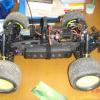
Zombi Posted January 2, 2015 Author Share Posted January 2, 2015 (edited) Some pics from 2 pack run today in prep for Sunday's trail day. Edited August 4, 2017 by Zombi 3 Quote Link to comment Share on other sites More sharing options...
Gaz! Posted January 2, 2015 Share Posted January 2, 2015 This is by far and away the best yeti I've seen!! Great work fella Quote Link to comment Share on other sites More sharing options...
jony nitro Posted January 2, 2015 Share Posted January 2, 2015 Couldn't agree more. Quote Link to comment Share on other sites More sharing options...
Zombi Posted January 2, 2015 Author Share Posted January 2, 2015 Thanks chaps - very much appreciated Quote Link to comment Share on other sites More sharing options...
Zombi Posted January 2, 2015 Author Share Posted January 2, 2015 (edited) I'm very happy with the set up now too. Because the beast got quite heavy (not least as I use 5+ amp packs), the standard shocks set up just wasn't working any more, the ride height just slumped. After some experimentation (and a rig that bounced more than Tigger at times!) I settled on replacing the stock rear shocks for the Axial white springs... http://www.axialracing.com/products/ax30214 For the front, I removed the 54mm springs and went with 90mm (which are sized for the rear) green and maxed the preload collar all the way down... http://www.axialracing.com/products/ax30215 Today's run over a bumpy farmer's field (which I use as my testing ground) at full speed showed me the shocks setup was finally good, as the suspension was flexing like crazy and gave me a nice, smooth ride. Job's a good en! Edited January 5, 2015 by Zombi Quote Link to comment Share on other sites More sharing options...
Zombi Posted January 4, 2015 Author Share Posted January 4, 2015 (edited) Pics from today's tailing. I must say I'm so impressed with the Tekin gear, the difference is huge. It really helped me keep up with the Wraith boys when crawling through the more technical, rocky areas as there was just no cogging. And it still has the top-end power for when we did some circuit racing. I'm going to have to remove the 1-inch light bar though; the Q-series just drown it out so it's pointless. I might well sell it off. Lastly, the waterproofing working a treat, the beast went for several big dips, as you'll see below. Edited August 4, 2017 by Zombi 1 Quote Link to comment Share on other sites More sharing options...
.AJ. Posted January 4, 2015 Share Posted January 4, 2015 What compound are your voodoo u4's? Quote Link to comment Share on other sites More sharing options...
Zombi Posted January 4, 2015 Author Share Posted January 4, 2015 After speaking to Matt Ottman, I chose gold as it's for wet and cold conditions 1 Quote Link to comment Share on other sites More sharing options...
.AJ. Posted January 4, 2015 Share Posted January 4, 2015 Cool, my set of Gold's are waiting at my local Parcel Farce depot ready to be picked up tomorrow Quote Link to comment Share on other sites More sharing options...
Zombi Posted January 4, 2015 Author Share Posted January 4, 2015 Nice, you'll like them mate. What wheels are you putting them on? I ask because I vented the tyres as my VP methods didn't come with venting options. Quote Link to comment Share on other sites More sharing options...
.AJ. Posted January 4, 2015 Share Posted January 4, 2015 Im sticking them on my Mayhem Trail Shooters, I bought the tyres from Crawler Innovations along with inserts and they vent the tryes before they ship them so they work properly Quote Link to comment Share on other sites More sharing options...
Zombi Posted January 4, 2015 Author Share Posted January 4, 2015 Ah yeah good stuff, they do. I went with 3 evenly spaced 2mm holes. I think he does the same, or it's maybe 4 - I forget Quote Link to comment Share on other sites More sharing options...
Zombi Posted January 4, 2015 Author Share Posted January 4, 2015 One other thing, I "siped" (American word for "scored", I think) the treads as covered in the leaflet you'll get with them. It made a big difference, I recommended it. Just get a cutting wheel on the dremel on the case. Quote Link to comment Share on other sites More sharing options...
.AJ. Posted January 4, 2015 Share Posted January 4, 2015 (edited) Yea Ive seen that on a thread over on RCC, also I see this the other day http://www.rccrawler.com/forum/axial-wraith/520278-voodoo-u4-trail-rock-mud-snow-mod.html Don't think I'll be butchering a brand set of tyres to this point just yet lol Edited January 4, 2015 by .AJ. Quote Link to comment Share on other sites More sharing options...
Zombi Posted January 4, 2015 Author Share Posted January 4, 2015 Ah yeah his winter mod! I'm not going to do that as it'd bring a tear to my eye to start removing lugs! Quote Link to comment Share on other sites More sharing options...
Daveyb84 Posted January 4, 2015 Share Posted January 4, 2015 Great pics and it looked awesome fun. Seeing your progress makes me want one even more 1 Quote Link to comment Share on other sites More sharing options...
Zombi Posted January 4, 2015 Author Share Posted January 4, 2015 Thanks! And yeah it was a really good day out on what turned out to be a fine (albeit bloody cold) day. Quote Link to comment Share on other sites More sharing options...
Zombi Posted January 5, 2015 Author Share Posted January 5, 2015 So it looks like running my lights off the balance port is causing 1 cell on all my 3S batteries to deplete faster than the other cells. Googling the issue, it seems that it's a known potential problem when doing this and running lots of, or high powered LEDs. So it looks like I have to re-think how I connect up the VP Q-Series. Preference would be to keep the switch in the fuel cell still. And I reckon I'll run the power straight from the ESC by soldering on a couple of wires to the + and - posts. Quote Link to comment Share on other sites More sharing options...
Zombi Posted January 8, 2015 Author Share Posted January 8, 2015 (edited) Project re-wire is complete. I started off sketching out how i wanted it to look. I've found that prep is the key when it comes to wiring up lights, rather than just launching into it, so I'd advise anyone to do the same. The only thing that changed is that I realised I didn't need the plug after the switch and before lights connectors. I went for three plugs; one for the QS, one for the rear and one spare should I need it in the future. Next was crimping the JST connectors. I used flexible silicone 22 AWG wire bought from eBay. As you can see, I decided to feed the rear lights plug through the hole in the fuel cell. I had to drill it out to 3mm though as it just wasn't wide enough and i damaged a wire when trying to feed it though. The three connectors twisted together at the ends, ready to be tinned and heat shrink in place. Soldering done and the fuel cell distribution portion complete. More crimping, this time for the power leads which will be connected to the ESC. To connect these on was straight forward enough - wires tinned with a decent amount of solder first. Then I heated the post until the solder at the top started to melt, then simply placed my wire between the iron and heated solder and pressed down gently. And boosh, we have power! Edited August 4, 2017 by Zombi Quote Link to comment Share on other sites More sharing options...
The Dark Knight Posted January 8, 2015 Share Posted January 8, 2015 Looking good so far. I've made a mess of trying to crimp jst's before so leave it to more experienced guys now. 1 Quote Link to comment Share on other sites More sharing options...
Zombi Posted January 8, 2015 Author Share Posted January 8, 2015 It's not too tricky to do if you have the right tool to do the job with. Were you using a proper crimper like the one above or just pliers? It's possible to use pliers, but it's really fiddly. Quote Link to comment Share on other sites More sharing options...
The Dark Knight Posted January 8, 2015 Share Posted January 8, 2015 I was just using pliers, I should probably invest in some proper crimpers. Quote Link to comment Share on other sites More sharing options...
Zombi Posted January 8, 2015 Author Share Posted January 8, 2015 Yeah they're only a tenner from HobbyKing. Quote Link to comment Share on other sites More sharing options...


Recommended Posts
Join the conversation
You can post now and register later. If you have an account, sign in now to post with your account.