Jump to content
  • Join our community

    Sign-up for free and join our friendly community to chat and share all things R/C!

Stampede...in need of love


Nitroholic

Recommended Posts

I had finished sorting out my Anderson and got it up and running....so I thought I might aw well carry on sorting out the RC fleet, and doing all those little things that had been at the back of my mind or in my little notebook of ideas and inspiration.


I opened up the cupboard and the old Stampede fell out. OK....you just volunteered!


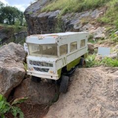
Now this was a pretty well used old beast, which I had bought off here for the princely sum of £50 to give the kids something to use while I was running bigger stuff. It had a 35A ESC and a ribbed can 3700KV motor, and also...when I looked...a few upgrades. RPM bumper, alloy front uprights and a wheelie bar. It got used and abused some more, got RPM rear arms after a rollover, a new van shell ( HPI Iron Outlaw job...very nice ) Then I stuck a HobbyWing bigger motor and 80A ESC in.....and they lost interest.


So what is the plan.


1) Repair the broken stuff .... I know the front bulkhead is cracked, the battery tie down is AWOL and the chassis is very grotty.

2) Make it a bit better and shinier.

3) Fill that horrid gap between the skinny Bandit chassis and the shell.....

4) Make a battery compartment that actually fits a variety of 2S packs...not just the hardcase ones I have.


Day 1:

Strip down is commenced, and hte truck broken down into 3 basic pieces. Front....rear...chassis middle. The plan is to replace the chassis with an alloy one from some sheet I have got from E-Bay for another project. The bit I need is marked off...and what is left is what I have to play with. Here's what I have...


zAsV8uZ.jpg


A rough strip is cut out from the 3mm plate,  which is the stock length and roughly the same width as the original. The front arm cutouts are lined up from the stock plastic item, and hte rear mount cut out. This means leaving a couple of tabs to slot into the rear bulkhead and fixed with 2 small screws. Not that rigid....so there is an opportunity to make something stronger here. The front fixing holes are drilled out at 4mm, again using hte original chassis as a pattern.


Tfg5JCl.jpg


A bit of tidying up and filing/sanding.....and the basic fit is fettled and looking all good.


1JdZuTZ.jpg


Now.....this is only part of the plan. I need to make a battery holder and some wider middle sections. I also want to thicken up the chassis to support hte alloy and prevent bending. So how do we do this...


Well...I plan a composite chassis. The alloy backbone will get some support and that support will form the battery tray and the side skirts to fill the gap in the middle. Back to the modelling software and the 3D printer. This chassis is too big for the small print bed I have, so it will be designed in sections. The sections will fit together with a series of steps using the anchor points naturally required for the other components. So......lets do the front first....


Day 2:

Out of the shed, and onto the computer.


A bit of head scratching and tinkering results in a design I think will work well. The section has to incorporate the servo mount and clear the front uprights. Holes were moulded in for the servo mount bolts and a recess left under neath for the servo tabs. The servo sits on the flat plate chassis to mimic hte original orientation, with the 3D printed piece on top sitting over the tabs. 4 3mm cap head bolts will run through from underneath. It will anchor at the front through the front bulkhead mounts, so 4mm clearance holes are modelled in.


jyZcUT4.jpg


A bit of a clean up, and on she goes. The bolts go through, and the servo is locked into place with 4 bolts and washers. Front bulkhead back in place and the shock tower and front body mount all fixed up. It will have to come apart again as the front bulkhead replacement part is not here yet...but I need to know the fit works. And it does.


vKmHcEA.jpg


Steering is all hooked up and the little recess at the back of hte front block is checked for battery fit. Snug and tidy. The battery has been moved as far forward as possible in this design to try and control the uncontrollable wheelies the truck suffered from before. Not the fun controllable type of wheelie...but the continual front wheels off the deck uncontrollable type. I reckon it will still lift the front a treat, but might still corner a bit too. Next job is to make the side pieces. They will fit over the front piece where it is stepped down, anchor on the lower brace mounts ( which will bolt through to moulded in captive nuts. The rear block will form the ESC mount and radio tray and also, I hope, provide an additional brace to the rear bulkhead.


  • Like 1
  • Thanks 1
Link to comment
Share on other sites

@DartmoorTrails ... cut was just a hacksaw/coping saw. Cut with a bit of spare, then scribe the correct line and file back to it. Just needs a bit of care, then sanding/deburring to leave a nice clean finish.


@TugThe chassis will add a bit of weight, but not too much. It's already packing more of a motor than Traxxas ever used, and by moving the balance point a bit further forward by relocating the battery, I hope to give it more neutral balance. Stock it's too tail heavy. Will have to see how it runs once I have finished. But...TBH...I can't make it handle much worse than a stock Stampy!


This morning...the new front bulkhead arrived...so I will get that swapped out before moving on to the next bit :)

  • Like 1
Link to comment
Share on other sites

1JK8eXx.jpg


Ughh.....horrid!


Rusty front pins were so bent I had to drift them out. The bulkhead is split and hte threaded sections where the chassis attaches were breaking up. Not to mention the mess the pivot holes were in. Hammered the pins back into true, cleaned up, greased and refitted to the new bulkhead. Much better.


3D printing the first side piece now, so lets see how that looks when it's done.I have built in the locating channels for a velcro battery strap, and some nice shaping. Will fill the gap between chassis and shell and widen it out to 140mm in the middle. No more big empty spaces under the shell for me!

Link to comment
Share on other sites

It's Day 4 .... and progress is being made.


Today I printed off the first of the side skirt pieces. Test fitrted it ...and realised all the things I should have thought about the first time....but that's projects for you.


1) Tyre clearance on full lock and full suspension travel....

2) Proper alignment with the shell

3) How tall the side piece needed to be to go up to the shell


All these things were wrong on effort number one.....but effort number 2 had them all covered.


fLXRKAb.jpg


The right hand side has a cutout piece to allow the wires coming from teh end of the pack to clear teh side of the battery box. The Turnigy softpacks I have all have wires exiting the side, and with the stock chassis they simply did not fit in the Stampede. so I wanted to cover that. The slot in the centre takes a velcro battery strap to hold down the pack firmly.  Captive nuts will go into both side pieces. They are a tight fit...but as you tighten them down, it pulls the nut in and holds it firm. Allows flush fitting.


rb3MrpA.jpg


Wires line up perfectly and run out without stress or strain. Good!


QbRNZOb.jpg


Wheel clearance checked on all 4 corners at full compression and full lock. Clearance at all points. Also good!


HQCB0uW.jpg


Shell sits about right, but I did notice thast the front and rear body posts are a bad fit in the shell. I need to move the rear tall posts I made before forward slightly as it is under tension and pulling the shell away from where the front body posts want it to be. That will be sorted.


t229OB5.jpg


From underneath...it just looks so nice not to have wide open spaces. Now I am thinking about an upper deck with a driver model ...... so it looks as good from the topside through the windows. But that's for another day!

Edited by Nitroholic
  • Like 2
Link to comment
Share on other sites

Day 5 ... and the final installment of the budget Stampede redesign.


The final section of the base layer is printed, which will fill in the back section, lock down on the side pieces and also attach to the rear bulkhead. The bolts that hold teh rear bulkhead toi the chassis go through this piece, and there is also a recess under the thing for a cable tie to hold down the ESC. 3 little 'blocks' on the part locate the ESC centrally so it's going nowhere.


HTORGs5.jpg


The piece is bolted down and the back end fixed in place with a pair of m3 bolts through the stock mounting points. Then the ESC is fitted and locked down with a cable tie.


S33DFGI.jpg


With the shell back on...she looks like this:


ETdegc0.jpg


Underneath...


1BCJHlZ.jpg


All that really remains to do is to stick down the on/off switch on the right hand side pod, and the same for the RX. Typically...I didnt have any double sided servo tape...or velcro tape...so I have had to order some. Will be here in a few days. In the meantime, the RX is cable tied to the bulkhead at the front, which is messy...but temporary.


Have I made the Stampede handle well...of course not.

Have I made it look nicer...I think so

Is it better ..... yes. Moving the battery weight forward helps a bit, plus the chassis is a bit more rigid. The shell fits to the car more like it should, and less crud should fly inside. I could make some wheelarch fill in pieces.....butI don't know if it would really do much to improve things. It's also different. And that really was the point here.

  • Like 1
Link to comment
Share on other sites

Nope...not using a box at all. The wiring will run under the battery and all I need is some servo tape to stick it down. 


Until that arrives, it's cable tied to the front bulkhead and not that secure. It's ok for testing.....but if it tumbled....I don't think it would stay. It will also get the battered stock shell back before I ramp it. The old HPI van shells are impossible to get now.

Link to comment
Share on other sites

Join the conversation

You can post now and register later. If you have an account, sign in now to post with your account.

Guest
Reply to this topic...

×   Pasted as rich text.   Paste as plain text instead

  Only 75 emoji are allowed.

×   Your link has been automatically embedded.   Display as a link instead

×   Your previous content has been restored.   Clear editor

×   You cannot paste images directly. Upload or insert images from URL.

Loading...
×
×
  • Create New...