Jump to content
  • Join our community

    Sign-up for free and join our friendly community to chat and share all things R/C!

Diary of a Losi 8ight 3.0 brushless conversion


Recommended Posts

Hi all


I'm currently going through the process of converting a 8ight 3.0 to brushless.  This is the diary of the experience.  Hopefully it might help anyone else thinking of doing something similar, or mostly just show how useless I am with hilarious/expensive consequence.


Step 0 was to order all the parts and here is my parts list:


- Losi 8ight Nitro kit.

- Losi 8ight Brushless Conversion Kit

- XERUN 150a with 2250kv Hobbywing sensored motor

- 3x 5600mah 4s Lipo packs

- Savox 20kg standard size servo

- jconcepts high flow body

- 2x Proline tarmac tire sets

- 2x Proline diamond offroad medium tire sets

- Some body cutting scissors

- Paint

- Masking tape - various widths


Things I learned during the ordering process

1. The standard 8ight-e 3.0 body doesn't fit the nitro version.  You need either a proline bulldog, jconcepts illuzion or a standard body for the 8ight-e 2.0.  This is due to the 8ight-e 3.0 chassis being thinner


2. Getting a body to fit that is in stock is no easy task.  eBay is probably your best bet.  It took 4 attempts in total to get one and its still not arrived yet so praying nothing else goes wrong


3. Choosing a motor and ESC combo is the hardest thing I ever did.  There is so much choice out there and opinions differ.  I can only hope my choice is a good one.  It came down to the XERUN vs the Quicrun.  The Quicrun is waterproof but does not do sensored whereas XERUN is sensored.  I'm strictly fair weather so splash proof is fine


4. Its hard to get motors and ESC from UK sellers.  Modelsport has lots of choice but lots not in stock and limited information such as sizes etc.  Wheelspin has a good selection of Tekin and Castle Creations, but these are big bucks and as a basher over a racer I decided to go a bit cheaper.  My top tip here is probably to shop around eBay.  In the end I went to RC Echo after a strong recommendation from a friend.  Item isn't here yet but it was dispatched quickly and is on its way.


Next post in here will be step 1, probably the only bit I'm good at, dismantling

Link to comment
Share on other sites

Step 1 of the conversion: Take out all the nitro bits to leave a nice empty space for the new conversion.


This is very straight forward.  There are a number of screws underneath to remove the bracket that supports the pipe, the engine blocks, the fuel tank, the radio/battery box and the centre diff housing.


One thing to be aware of, is that some of the screws are metric and others are imperial, so you'll need some hex drivers for both.  I might at some point switch these all to metric to make it easier but for now its fine


The centre diff is retained and will be used in step 2 so at this stage you can dismantle the housing.  Theres a bunch of screws on the top plate you will need to take off but it comes apart pretty easily.  The diff then slides out of the brakes really easily.


My top tip at this stage is that as you take screws out loosely screw them back into the thing they came out of.  That way if you plan to convert back at anytime it should be really easy in reverse.


Link to comment
Share on other sites

Would it not have been easier and cheaper to buy the RTR electric rather than the Nitro kit?


Its only

Edited by hebby
Link to comment
Share on other sites

Potentially yes, but where would be the fun in that :-)


Actually you can do it quite a bit cheaper.  My reasons are as follows:


- The nitro 3.0 kit was on sale for only

Link to comment
Share on other sites

Step 2: Changing the spur gear


So firstly I'm going to admit I don't understand gearing.  Its next on my list of things to learn but I'm more interested in getting the car up and running.  I have come across this http://teamassociated.com/pdf/cars_and_trucks/shared/gear_ratios.pdf and I might read it but if anyone has a dummies guide I'd highly appreciate it.


So for now, we will trust in Losi that I need to change the nitro spur gear (48) for the electric one (45).  To do this it's pretty simple


1. Take the centre diff you removed and identify 4 screws holding on the spur


2. Take those off and remove the spur (being careful not to spill diff oil everywere


3. Carefully remove the diff gear on the inside of the spur to uncover a pin.  Use something flat to help leverage this off if you need to


4. Now take the pin out and remove the shim if there is one. 


5. Slide out the drive cup and remove the blue gasket and orange rubber seal.  You can reuse these if like mine its pretty new


6. Take the new spur gear and note that it comes in two parts.  A centre piece that slips into the spur gear


7. Put the gaskets in as they came out and slide the drive cup back through.  Add the shim and and pop the pin back through to hold it together


8. Put the diff gear back over the pin and carefully place it back on and put the 4 screws in.  It might make sense to add a tiny drop of loctite for this.


So thats it.  What did I learn doing this?


Firstly its really simple, I always get worried servicing diffs but realise they are not as scary as they look.


I added some more diff oil because there was a bit of residue left on the inside of the spur.  


There is a bearing on the outside of the old spur gear.  In practice this didn't seem to want to come off.  I'm sure with more force it will but I was worried about damaging it.  In the end I decided to just to buy a pack of new ones for around

Edited by evilhomer
Link to comment
Share on other sites

Step 3: Fit centre diff to housing


This step is really simple.  You take part of the previous housing and the new engine mount included in the kit, then use a new top plate to hold it all together.  It's pretty hard to go wrong.


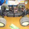
This almost completes everything now and its just a case of putting everything onto the chassis, fitting the motor etc.


Link to comment
Share on other sites

Step 4: Fit the drive


Next step for me is to fit the centre diff back into the chassis.  The conversion kit is pretty good here as it reuses many of the holes vacated by the nitro bits.  


Obviously remember to fit the drive shafts.


In addition there is an motor bracket here.  I've read a few people suggest not to fit this as chassis flex can cause it to move the motor.  I'm undecided yet.  If anyone wants to comment here with their experiences I'd appreciate the advice, otherwise I'll probably try both ways and see how the motor sits with and without the motor bracket.


Link to comment
Share on other sites

I can't believe I've just found this thread I've just finished the exact same conversion (except for diff combo and a few other bits).

I've made the mistake of buying a 3.0 e shell and as you've said it don't fit!!! Gutted so glad you listed a few alternatives I was lost as to what to get. Now I know Lols

I will be following this thread closely. Good job on the guide wish I'd seen it before I'd started mine though

  • Like 1
Link to comment
Share on other sites

@Morpet - Glad you like it, I'm really learning this as I go along.  My thoughts are that its easier than I originally thought it would be, but I've learnt quite a lot so far in the process.  I fitted the battery tray and the radio box yesterday so pics of that coming up soon.


My biggest challenges were body and also my motor uses M3 screws rather than the M4 supplied with the kit so I'm now trying to work that bit out.  Also being pretty new to electric having spent the last few years on Petrol I was confused on the connectors I should use.  In the end I've decided to convert ESC to 5.5mm bullets to match the battery.  Now just got to get brave and start soldering.  If you see a lot of fire just a bit North of London either I did something wrong or breakfast got burnt.


The biggest challenge so far has been getting parts.  Motors and ESCs seem to be more readily available abroad, but I used RC Echo and it arrived within a week so was very impressed.  eBay is fast becoming a great source of RC goodness.


Other learning is that forums are a saviour.  In the old days you'd go down to a hobby store and they'd explain everything but trying to learn all this as I go along means I've found a lot from just chatting to people here and on other forums

Link to comment
Share on other sites

Sorry for the few days silence on my build, I got distracted by a hexacopter build and some (lack of) soldering skills...


So.  I continued the build and here goes


Step 5: Install the radio box and battery tray


This bit was really straight forward.  Using the supplied screws, fit it all in.  It's pretty obvious where they go.  The only issue I had was getting the battery tray all lined up. For this I found it easier to loosely attach all the screws then afterwards tighten them all up


Link to comment
Share on other sites

Step 6: Install the motor


Here is where things got interesting for me.  In theory it should be a case of screwing the thing in.  I had a bit of a nightmare.  The losi kit comes with M4 screws which don't fit the fixings on the hobbywing motor.  I trundled down to my local RC and hardware store, and was pointed to a rack of screws.  I couldn't find anything with M3 written on it so I asked and was told they are probably M3.


When I got home I found the screws didn't fit.  Initially my suspicion was that the holes weren't M3 so I stole a couple of screws from my Firestorm and they fit.  I checked the manual and they said M3, the tech specs on the Hobbywing also said M3.  So I ordered some new M3s and the engine is now mounted.


It was a bit fiddly.  To get it in snug I had to put the screws in lose then slide the motor in and tighten them up once in the bracket.  This was a pain to get to but was sorted.  I then had to tighten the grub screw in on my new pinion which is the 15t and it seems to fit nice.  I just need to test and make sure the mesh is good.


The next step was to solder some new bullet connectors to the ESC.  I tried this with my Dremel Versatip and got a nice tin on the connector but really struggled to tin the thick cable and get it to join.  I'm not convinced by the soldering job so in the end I went and got a decent but well priced Weller 80w and I plan to redo the connectors with this hoping that I can get better heat quickly into the join and create a better connection.  I'll update on that as my next step.


So the car is nearly complete, left to do:

1. Sort the ESC connectors and attach it to the car (how do people do this?  With 3M sticky pads?  Velcro? what is best?)

2. Install my Savox servo

3. Paint the shell (took ages to get the right paint.  I won't spoil the final reveal but I hope its going to look a stunner even with my poor spraying skills)

4. Finish gluing all the tyres to wheels (hopefully avoid my fingers this time)

5. Drive it like I stole it


Link to comment
Share on other sites

Looking good, at almost the polar opposite of my conversions so far - as in this is a no corners cut job and I do mine as a make do (nitro chassis?  It'll do!  Nitro shell?  Ditto! etc).


Interesting point re chassis flex and motor mount.  It's not something I've considered, as i'm considering a rear motor 'brace/mount' for the 4274 in my ST Pro conversion.  I figured on wanting it as the weight of the can and how it's suspended by only 2 M3's meant that on heavy landings there would be a lot of force involved.  Now do I want chassis flex or not?  The Pro has cnc braces so I'm figuring they'll minimise movement anyway so that helps, but how about driving the thing?  To flex or not?  The Hong Nor Pro Buggy i'm slowly doing takes things one step further to minimise flex and has a lovely thick cnc cut Z shaped brace on top of front and rear cnc braces - come to think of it the ST Pro's centre diff mount prob does similar.


So Flex or No flex?

Link to comment
Share on other sites

Stage 7: Fit the ESC and servo and she lives!


She lives!  So far she's had a test drive around my living room and nothing exploded!  I'm ruling that a total success.


First thing I had to do here was solder new connectors to the ESC.  I am literally useless at soldering having only done it a handful of times.  I bought a new 80w weller iron for the job and already had flux and solder from the recent DJI F550 build.  I had tried previously but wasn't happy with the job so this was attempt 2.  With the new iron it was a lot easier.  I won't go as far as to say its perfect.  The solder could be shinier but its not quite that horrid cold grey either.  Regardless I'm sticking with it now I don't think I'll make it better.


I'm using 5.5mm bullets.  I was planning on using Deans connectors but it was easier to change one ESC cable rather than lots of batteries and they seem pretty nice connectors.


If you have to do this my tip is take your time!


Then it was on to the servo.  I installed a nice new Savox (having used them in previous cars and had great service from them all).  I have a couple of tips here


1. Firstly, when installing the steering link I ended up taking the radio box out again as it was tricky to get in and I needed a bolt as well.

2. Turn on the transmitter and car before seating the servo arm to make sure its in the right position

3. Be careful on the size of screws, I found there is little clearance room around that area and things can knock about.


So what is left to do?  Very little, I need to prep the body, try and unstick my fingers from gluing tyres onto wheels (which by the way top tip, seat them on first and check orientation.  My tread is directional and nearly made a stupid mistake of having some point the wrong way), then paint it.


Hopefully with a clear day on Saturday the shell could be sprayed and the final reveal will be made. 


Link to comment
Share on other sites

I'm unsure on the flex/motor brace topic.  At some point I'm going to get the CNC braces no doubt but it all seems pretty stable with the motor brace currently installed.


I'm tempted to take it off and try both, actually even with only two screws, because of the slider it actually fits very snug against the motor mount so not sure the brace underneath is definitely going to be needed.


I'm probably over thinking this to be honest.  I've broken far more expensive bits on the Baja.  If I can the shell painted, there is a chance she might make an appearance at a Bash on Sunday

Link to comment
Share on other sites

  • 2 weeks later...

Hi all


So the final reveal!


I've painted the shell in Martini Racing Colours.  I struggled to get decals for 1/8 scale but found the 1/10th scale I got on eBay was enough.


It's not a perfect paint job but I'm pretty poor at this generally so I'm declaring this my best shell so far.


Couple of things worth noting


1. With a big 4s pack on its pretty tight in there.  I'll probably put some velcro on the sides to help it out a little as it sits a bit wonky with the cables pushing it up


2. I wanted to try and protect the paint job a bit.  I was going to use drywall and shoo glue but in the end I decided on using gorilla tape.  this seems to have made it a bit more sturdy


3. I'll probably order some bumpers as I use this for bashing its likely to take a few hits


4. I did take it for a quick run but on the first straight, the ESC blew up.  I ended up ordering a Castle Mamba 2 2200kv and 6s ESC combo and putting that in the car.  Oh my god, the speed is literally insane!  I highly recommend this


5. I did get the ESC replaced so I now have a hobbywing Xerun combo and I'm now bored so need a new project.  Thinking of getting an Xray XB8e as I wouldn't need much more than another servo and receiver to add to it


Enjoy the latest pictures


  • Like 2
Link to comment
Share on other sites

  • 2 weeks later...

Join the conversation

You can post now and register later. If you have an account, sign in now to post with your account.

Guest
Reply to this topic...

×   Pasted as rich text.   Paste as plain text instead

  Only 75 emoji are allowed.

×   Your link has been automatically embedded.   Display as a link instead

×   Your previous content has been restored.   Clear editor

×   You cannot paste images directly. Upload or insert images from URL.

Loading...
×
×
  • Create New...