Jump to content
  • Join our community

    Sign-up for free and join our friendly community to chat and share all things R/C!

LC Racing EMB-T Pro (1/14 Truggy)


Rebel158

Recommended Posts

Well, it’s built! My first ever end to end RC car build, and micro/mini no less!


I had started out with the intention of taking photos during the various phases of the build but found that I became so immersed in the build that I neglected to capture key moments, so the completed item will have to do. To be fair the end results throughout the build are no different to those captured in other threads.


In summary, the build went quite well, and as expected, with no major ‘gotchas’. However, due to the scale of this kit, some parts are a little fiddly but overall not too bad, especially for my short sausage fingers! In fact the diffs went together first time, and without issue, as did the shocks, and pretty much everything else (it helps to have a decent illuminated magnifier, and micro tweezers, amongst other tools!)


For the oils I went as follows (based upon Darren at DMS’s recommendations)


  • Front Diff: 5000
  • Rear Diff: 3000
  • Front Shocks: 450
  • Rear Shocks: 350


‘Gotchas’


Well, there were bound to be some, but nothing I couldn’t overcome with lots of coffee and snacks!


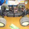
ESC placement - Mine is the ‘Pro’ kit, which came with the larger 60a esc, and is larger in footprint and height than the standard 35a offering, so a little more challenging to shoehorn in.

Solution: The pre connected motor cables are removable (not soldered) so I was able to squeeze it in between the motor and the servo, and connect the motor direct to the esc (the motor comes with pre soldered cables) although care needs to be taken with flexing the cables into position. I also used threadlock on the servo securing bolts, in the event that the esc pushes against the servo body (the esc is pretty secure anyway)


20240217_120509.thumb.jpg.ab4abd6b9d351cf176c87718043bd202.jpg


Battery size and placement - Probably the most challenging part of the build as you are limited in the battery size you can use due to a number of factors. The standard kit comes with a fairly robust (if chunky) top deck, which reduces the available height a little. The main issue for me was the battery width as i) the supplied battery ‘holders’ are quite narrow, and foul slightly on the chassis buffers, thus limiting your options, and ii) too wide a battery will foul against the drive shaft.

Solution: The Pro kit came with a carbon fibre top deck, which is much slimmer in profile, and means that the battery height is less of an issue. I have a new Turnigy 2s battery that I wanted to make use of, so I resolved to trim the plastic chassis slightly to gain as much width as possible. I also sourced some heavy duty velcro via Amazon, which appears to secure the battery pack very well, allowing a couple of mm between the battery and the drive shaft. We’ll see how it holds up in practice. For reference, my battery pack dimensions are L:105mm x W: 35mm x H: 18mm (excluding cable protrusion)


20240217_120223.thumb.jpg.8530a5f61b24dc07a288776aee8b0324.jpg

20240217_120002.thumb.jpg.fa05ad3e758e8a17961031185274855a.jpg

20240217_120558.thumb.jpg.f4163a377522859dd61eeb81bd18bf5b.jpg


Receiver placement - The Turnigy GT5s receiver that I have is a little too wide, and tall to sit atop the servo, and under the top deck.

Solution: I resolved to place it on the chassis floor, just in front of the battery. The antenna wire I secured by shaping and stick a piece of velcro backing to the top deck and boreing two small holes through the velcro (the velcro backing is fairly rigid and provides ample support) Through these holes I was able to thread the antenna, and I also sleeved it with a length of wire shrink wrap, so that the antenna sits upright, towards the front of the car.


20240217_120255.thumb.jpg.9966065170205be71989e243236e2eb7.jpg


Screws/bolts etc - There isn’t much to say here, save to say that it would be prudent to have a decent set of digital calipers to measure the bolts etc. The associated bolt length and diameter is specified throughout the build instructions but I did find myself using the wrong bolts on occasion, and having to reverse my errors, and this is where the calipers came in very handy, although the manufacturer’s tolerances can be fairly ‘loose’.

Solution: Digital callipers. Spare screws.


Turnbuckle end caps/joints - Yep, I was caught out by the opposite handed thread and spent AGES trying to figure out why one end joint per arm wouldn’t catch!

Solution - Similar build threads on this forum!


Items of note, and the way I’ve pieced it together…


In past threads I have read that the instruction build manual wasn’t particularly clear, and that key details such as the slipper clutch setting were not covered. I’m pleased to say that the manual does appear to cover this, and other areas not previously referenced. This is the 2022 spec kit (the latest as far as I’m aware) so perhaps past comments have been taken on board by LC Racing.


Slipper clutch - I have set this at 7mm from the end of the shaft as per the manual and will see how it runs.


Slipper shaft assembly - A few have mentioned play between the bearing and collar/spacer at the differential pinion end, and as a result have installed a second bearing. It looks like LCR might have addressed this as I did not note any such play, nor any additional space available for an additional bearing (ref step 4 in the manual below)


20240217_123150.thumb.jpg.fefd34e25828365bef0abc37c6a1ac18.jpg


ESC to battery connection - The ESC comes pre fitted with a Deans connector, and my battery (Turnigy Nano-Tech 2.25 2s 65-130c) comes pre fitted with a XT60 connector. Rather than mess about with chopping and soldering I opted for a male Deans to female XT60 connector. 


20240217_120519.thumb.jpg.337b890e94e77b6705425b54624b397d.jpg


Motor pinion - Three are supplied in the Pro kit. I opted for the middle sized option (circa 9mm diameter if memory serves) as the supplied grub screws only appeared to fit this and the larger pinion, so we’ll see how this setup runs.


Body shell - The supplied body shell is clear, and whilst I intend to paint it at some stage (along with another spare that I acquired) I also opted for a pre painted shell, which costs only a few £s more than a clear shell. You can never have too many spares, especially as this will be a light ‘basher’.


Wheels/tyres - The standard pre mounted truggy items are supplied. I also picked up a set of the monster truck pre mounted wheels which work out to the same diameter (the monster wheels are smaller, but the tyres larger) which I have installed for now.


Rear shock mount - The manual specifies 6mm length screws up top, and 8mm below. Deciding these might be a weak area I added a couple of nuts to the bottom screws to provide a little more strength in this area.


20240217_120412.thumb.jpg.f52b8440fe0aac7253a3af06282b595b.jpg


Rear wing - A black nylon item is supplied. I purchased a spare (yellow) which I chose for a splash of colour!


Potential Upgrades…


No major plans at this stage, but items such as a servo saver, monster truck front bumper, and metal turnbuckle end caps/joints might be an option depending on how the standard setup holds up.


The finished item!


20240217_115900.thumb.jpg.9950e1bb3033d9c75eac8d8cb3badc01.jpg


20240217_115817.thumb.jpg.d594bb0136bb5e7b2bf51f38750c9641.jpg

20240217_120509.jpg

  • Like 1
Link to comment
Share on other sites

Join the conversation

You can post now and register later. If you have an account, sign in now to post with your account.

Guest
Reply to this topic...

×   Pasted as rich text.   Paste as plain text instead

  Only 75 emoji are allowed.

×   Your link has been automatically embedded.   Display as a link instead

×   Your previous content has been restored.   Clear editor

×   You cannot paste images directly. Upload or insert images from URL.

Loading...
×
×
  • Create New...