Hello all,
Always fancied building and designing an rc car by myself so now I have the resources to I am and here's me building myself a Tumbler Batmobile from the 2005 Batman films.
What I wanted to achieve is a durable rc car that shows scratches and dents if it happens to hit something as well as functions like the real car with gears so working with metal at work I decided to use metal to make my car. Because of this I'll slowly work towards making it more accurate to the real thing but for now I'm aiming within it resembling the Batmobile with simple panels so it will be instantly recognised.
I started back in October 2012 so will try to show the steps leading upto where I am now as best as I can and plenty of pics too (when I remember to take them) so any questions or extra pics and info you want to know just ask and I'll try to help answer them and maybe learn something too myself.
I started by finding the overall measurements of the Tumbler off the internet and researched for wheels I could buy to give a fairly accurate scale size. I ended up buying 1/10th buggy wheels for the front (slightly narrower than scale but fit well) and 1/8th buggy wheels on the back (just slightly bigger diameter but good width) which would then give me a 1/10 scale to work to. I copied the overall width, length and wheelbase onto a piece of cardboard and cut out the shadow of the wheels in cardboard too so I could move them around where I wanted them then take measurements like below. Guessing how much steering angle for the wheels I would need proved to be a bit of a lengthy process as I had to account for what materials I had acess too to make the front suspension arms.
Then I began making a chassis from 13mm box to give me ideas in my head how it will fit together and work. The wheels and diff are from my old car that made me despise plastic parts from being easy to break and the engine was a 0.28 I bought to upgrade it before I ran out of spares so needed to make parts for a car to drive again anyway.
When my new wheels arrived I began designing the rear axle shafts to give me twin rear wheels, this was done using Draftsight a 2D CAD program that is free however a few weeks later I gained access to Solidworks which has been a great designing tool. The axles are 10mm steel bar with M10 nuts TIG welded on that fit into the wheels with a driveshaft joint drilled into the end on the lathe and the 2mm slot cut with a grinder cutting disc very carefully. I may go back to these one day as they are a bit too heavy duty due to using 10x19x5mm bearings. 6 sets (5 spares) were made of these
This is an axle with both wheels attached onto it using a various selection of washers and nuts as spacers currently
After this I then placed the wheels with my chassis to see how it would look. I later shortened the nose of the chassis as I began finding better pictures on the internet that showed the nose is set further back in of the front wheels.
Then I started using cardboard again to start getting ideas for the bodywork so I knew how much space I was going to be left with inside for the engine and radio equiopment etc. At this point my bedroom floor not being flat was starting to turn into a challenge to keep the wheels in one place.
Then a venture out into the garage and began cutting out the flat pieces of cardboard in 1.2mm steel which is a bit too heavy duty again so weight began building up very quickly. Also I realised that it would have been far easier to have cut it out as one big flat piece then bend to the correct shape than to try holding the parts in place and burn my fingertips welding them together
Then I began working on some of the mechanicals to get the functionality on target. this involved making the front axle shafts in a very similar way to the rears, boring out some 25mm bar to fit the bearings and then drilling pivot holes to accept M4 bolts with 6mm bar drilled to 4.1mm to act as a bearing in the hub so that it wears out first then I just need to replace that one part. The hubs were made from 25x3mm flat steel bar and when I later got the steering working I then needed to keep grinding it away to give me the clearance for being able to turn the wheels enough so the turning circle is acceptable. Currently not many of the moving parts are on bearings due to excitement to get the first version working and also the cost of buying bearings I may not use but redesigning the suspension with bearings is on my mind for a later time.
At this point I gained access to Solidworks hich has been a really good tool and saved me plenty of time and money. This meant I was able to start designing the steering geometry and parts which consist mainly of 4mm bar threaded on the ends into small motorsport grade rose joints which have ben shortened. Making the threaded bar for the two front rose joints was a bit tricky as I kept damaging the thread as the part is only 8mm long. Excuse the masking tape, that's now been replaced with a very frankenstein part which the shafts bolt into but if I accidentally crashed into something solid they will spin before damaging the steering servo.
Next I went back to the bodywork once I was satisfied with the steering linkage and how it functioned which involved alot of grinding away the chassis metal holding on the front arms towards the middle as it allowed the arms to move up and down freely with the wheels pointed whichever, the steering also works such that one arm can move up and down but both wheels still point straight ahead so handling should be a bit more stable.
I found plenty of pictures and spent many hours studying the films trying to work out how to make and simplify the construction of the panels yet still keep the overall look as well as it all being able to be dismantled easily for maintenance. I managed to get it down to the front arm panel that moves with the suspension, side panel that continues the contour of the arm panel and upto the roof panel so that I have managed to maintain some of the key contours of the panels although slightly altered to suit the car's dimensions. I also want the rear air brakes to work when the brakes are applied so I'll later design the linkage to make them work off the throttle/brake servo. I've based the designs for these panels on the sides to be made from 1mm thick aluminium as I've realised weight has started to become an issue as it's estimated around 7.5kg!
After I was happy with these designs I again went out in the garage and began making these panels. I printed out the flat shape of the panels then drew round them on the aluminium and cut it out with a pair of metal shears then drilled all the holes so that I can bolt the panels onto the chassis. I used a metal folder to create all the bends, much easier with one of these than beating the panels with a hammer and denting them before they even see the car.
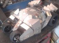
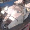
I used the same method for all of the panels except for the air brakes which are from 1.2mm steel TIG welded onto 4mm bar and currently bolted on. A few holes drilled later and the car looked like this.
It's not perfect to the real car as I've simplified it heavily for now but I want to go back to it one day and re-assess the panels and maybe get them laser cut so that I don't have issues with blunt drill bits making holes wander a few mm, it probably weighs the best part of 4kg like this and that is before the rear axle has even been fitted.
In the last 2 weeks I've been concentrating on getting it as a rolling shell and near to being driveable. Because of the proposed weight now being around 7.5kg and that the real car has gears I fancied a go at making my own automatic gearbox for it so that the clutch stands a chance of lasting more than a few hill starts. I've managed to get the first design down to 36mm wide for 3 speeds using module 1 steel spur gears that I have to turn down to get them that narrow. First is closest to the engine then second and third gear sets with first having a one way bearing pressed inside it then I'm going to try to use the centrifugal clutch in second gear hub as a one way bearing too when third engases by having the clutch shoe shaped to only work one way however I'm not so certain about the lifespan of these parts but it's worth a go I reckon. In the second picture you can see these shoes with 3rd in the position it would lock into third gear, for small adjustment I'm going tohave a bolt in the gear hubs that can be wound in or out to give a small amunt of adjustment without needing to disassemble and modify the springs.
And this is the current proposed engine position, I wanted to keep the rear live axle but making the casing was going to be a bit tricky so I'm going to try making a live axle that is belt driven so could have some interesting results. I also decided this because I found for the gear ratio I need I would require a lot of gearing down although I would like it to be adjustable for the future as it's currently geared to be 50mph flat out which I don't think it will be able to achieve this, if the engine was mounted transversely which seemed to be a good idea in my head as it gave plenty of space for the gears etc and also spreads the weight around a bit as well as I can use the bearing blocks to hold other parts like the front springs and tuck the radio equipment in all the gaps that are left.
Now I have started working on the rear axle, given the length of the belt and the scale size I reckon the the belt will be able to twist slightly to give roll in the rear suspension providing a tensior is used to keep it from jumping off the guide flanges fitted to the pulleys. Also thanks to one way bearings I've managed to come up with a compact diff for it too as being a vehicle that could have very strange straight line handling and also could be used off road I didn't want to use a conventional diff where one wheel could slip and a slipper diff was too complicated to justify bothering to make one.
Currently I'm working on getting all of these newly designed drivetrain parts designed so I can then assess whether they will work well enough or not otherwise this is now up to date with where I am. I apologise for the length and if you have fallen asleep sorry . It's something different I think people may want to see and follow it's progress as I'm determined to finish it.