
- Popular Post


cooper_xl
-
Posts
188 -
Joined
-
Last visited
-
Days Won
3
Content Type
Profiles
Forums
Prizes
MSUK-Forum - RC Model News and Community
Articles
Events
Posts posted by cooper_xl
-
-
M548
in General RC
Non-rc people can think all they want of adults playing with expensive toy trucks but this hobby has a nice learning aspect . Who learn about a lot of details of the trucks you're building and how they work. Another thing is learning skills. I've learned to TIG and braze because of RCs. I've learned to 3D model because of RCs . Building the M548, learned even to use Adobe Illustrator to do this next thing:

On Facebook, through the contacts network, came to know a army mechanic who works on the only base that have our M548s. He liked my project and offered to take photos of anything I wanted(WHY DIDN'T HAPPENED EARLIER!!) . He sent the photos of all I've needed: Tags and labels around the truck and inside the cockpit.
After that, on Illustrator redone every label to vetor, including text in the right font and size so it wouldn't be messed up when printed in scale. Then a local print shop agreed to print these properly. All the text is clear
-
 1
1
-
-
M548
in General RC
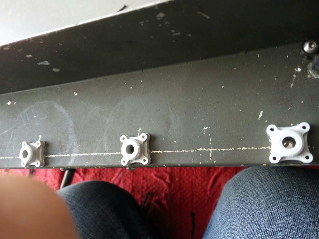
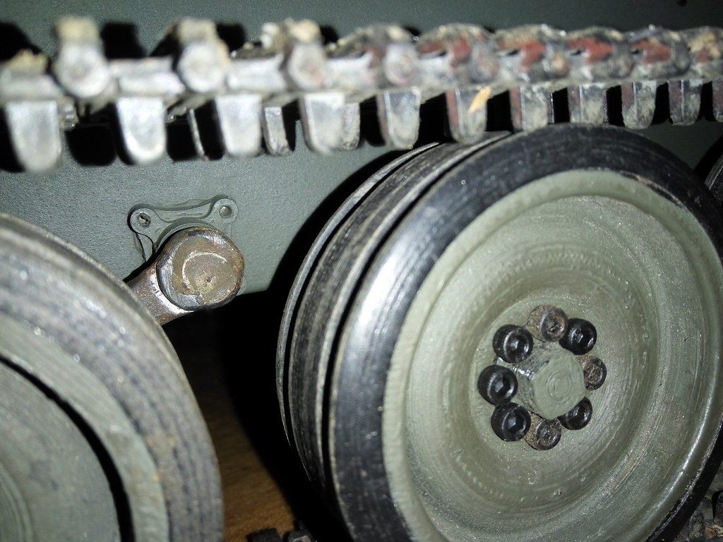
Now a small detail that it's almost invisible but wanted to do it anyway
Each road wheel arm has a piece atached to the hull where the axle pivots
So printed 8 of these:
OD green paint to cover it allThese were meant to be bolted on but only glued them on
-
1
-
-
M548
in General RC
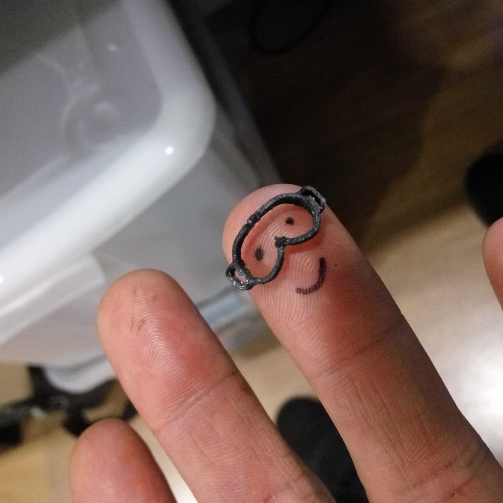
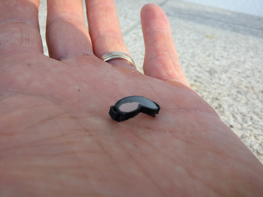
Dollhouse stuff:
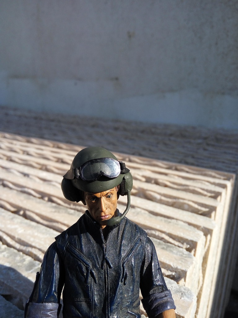
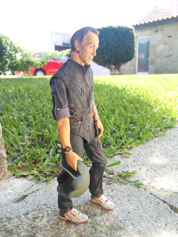
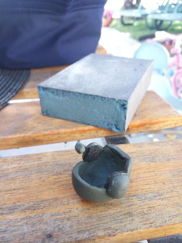
Thought that the operator needed some goggles for his helmet. The first idea was to scratchbuild everything but my Dremel broke so I've copied the goggles' frame from a real army model and 3d printed it.The lens are from a bit of clear package plastic and the strap is a strip of bicycle inner tube
And:
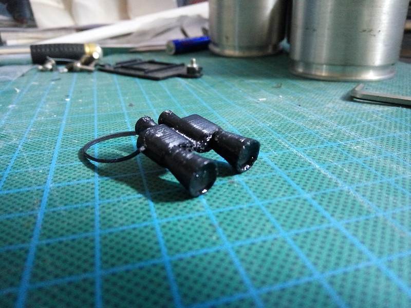
The binoculars are printed, the strap is a strip of rubber and for the lenses, I put a drop of green threadlock in place(designed those parts like small cups)They work pretty well:
-
2
-
-
- Popular Post
- Popular Post
Got these 2.2" Roost to mount the big Deep Woods on the AR60s. I have both for a long time still with no clear idea on what I'll do with them

-
7
-
M548
in General RC
More on the drivetrain.
Some rubber over the sheetmetal to cover 2 previous holes from the first gearboxes and try to suppress some noise
(this print was so ugly but I kept it for testing purposes...until now 🙂 )
And a small rubber lip on the cover to keep sand and dirt away-
2
-
-
M548
in General RC
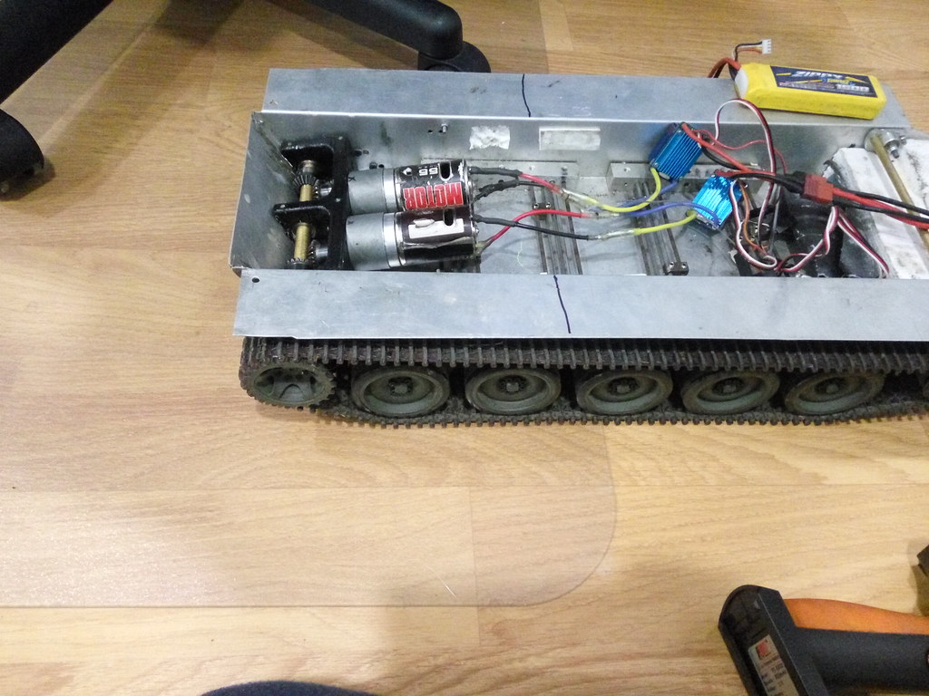
There it is,assembled and working. Just need a cover to reduce some noise and prevent that some LED wires don't get caught on the gears. The electronics were not in place because I'm was about to take everything out to paint the hull
There's some video.Sorry about the backgroundNeeded something on top to keep away dirt and sand
First idea was a standard cover but started to mess with the 3d printer and decided to do a more elaborate clear cover to see the gears working(might sound like a joke but many non-rc people who see this truck don't understand how this truck moves or why it needs 2 motors...)-
2
-
-
M548
in General RC
27 minutes ago, Stormbringer said:i run a couple of the Taigen/Heng Long tanks and they have the steel gears and they seem well up to the job

They have silver or black gears? I've saw aftermarket sets with black gears that seemed strong and better made. The problem could be from the 540 I've used from the start. I've should kept the 370s,just to see if they handled the weight.
-
M548
in General RC
13 minutes ago, Stormbringer said:thats really neat and good bit smaller than the heng long gear boxes
were the HL boxes plastic or metal geared ?
I avoided the plastic ones but the metal on the ones I've bought was that silver,soft metal. Aluminium, maybe
-
M548
in General RC
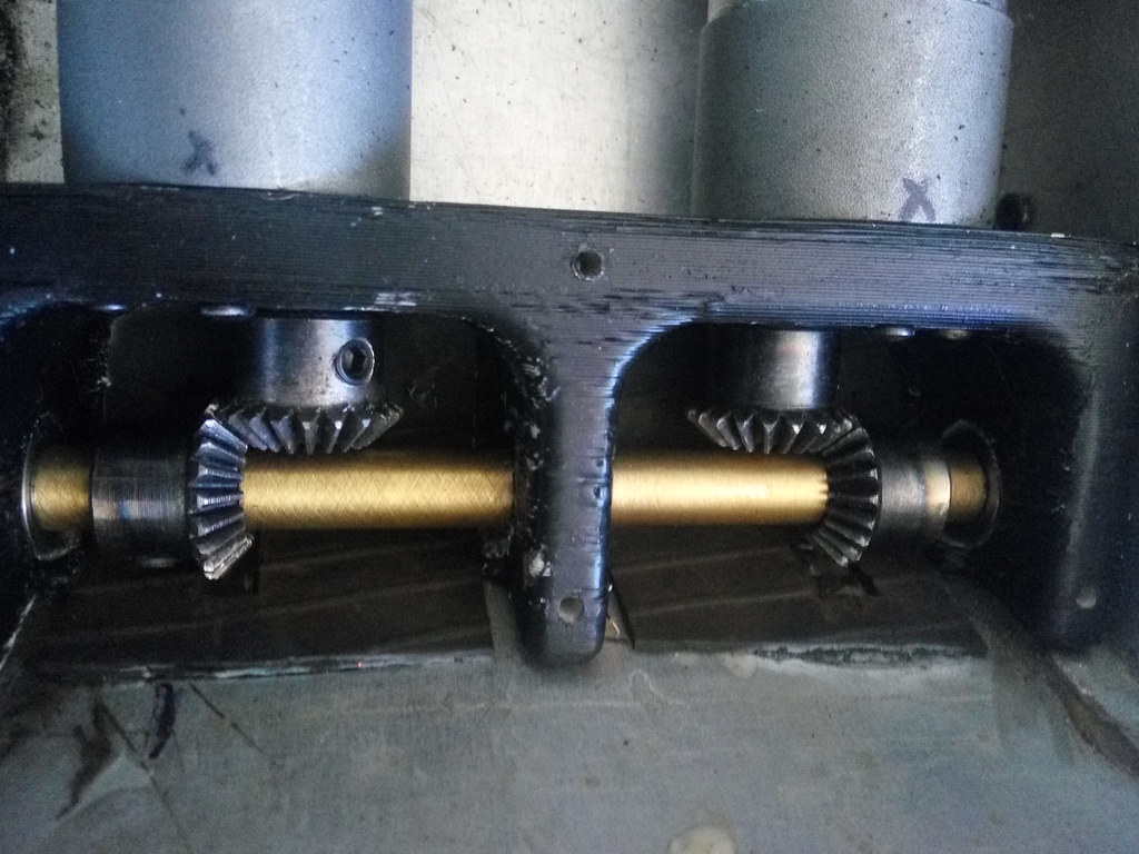
Now, something more interesting: drivetrain!
The henglong gearboxes are not up to the task. Went through 2 sets (one lasted 5 minutes)
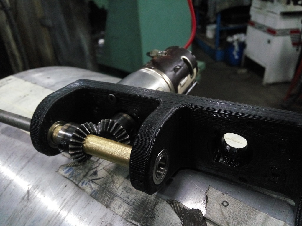
Switched to these gearboxes:
First ordered a 33:1 to test:
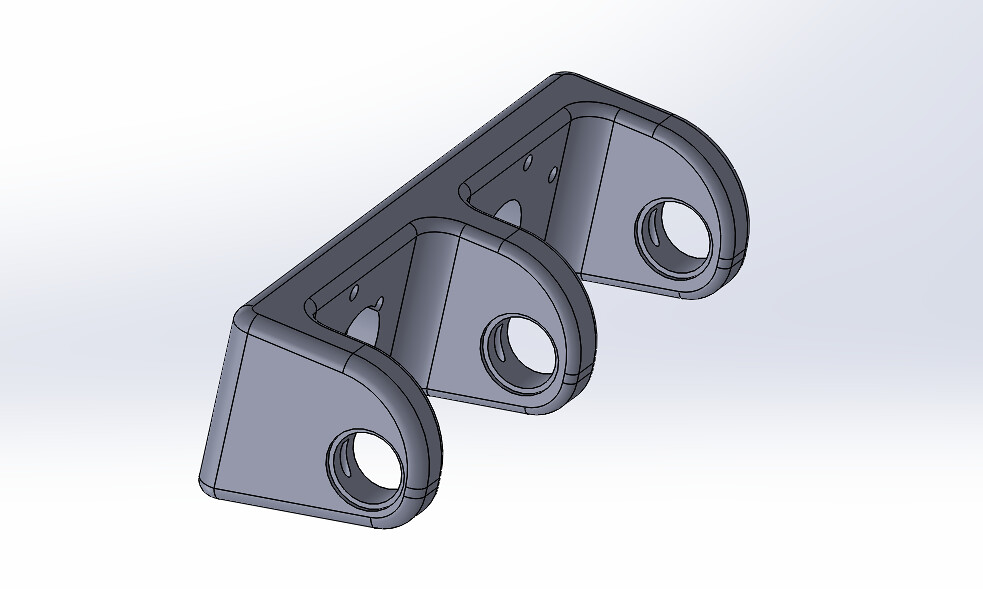
Thought of machining the structure but 3D printing could do the job
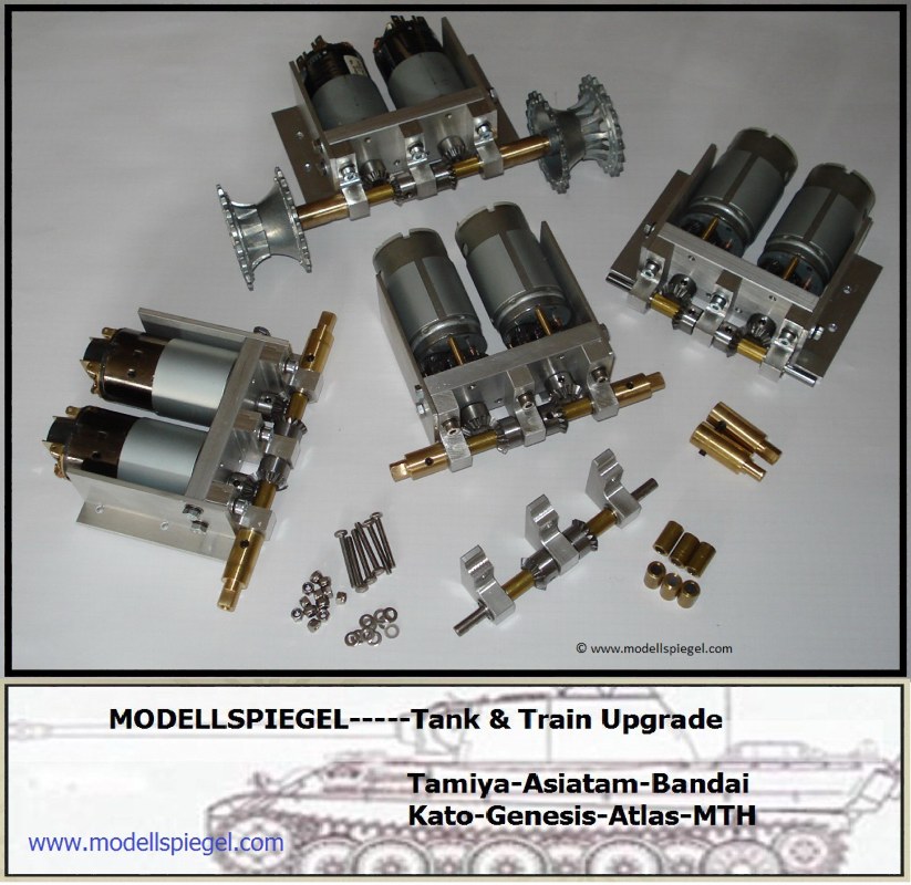
First of all, I'll not say that this was my original creationThere's a german shop https://www.modellspiegel.com/ who created and sells these gearboxes for 1/16 tanks:
I had several ideas for the new drivetrain and the chosen was heavily influenced by this layout above
I'm not in condition of forking out all that money and also like to do things myself as much as possible. And I doubt that would fit in my truck
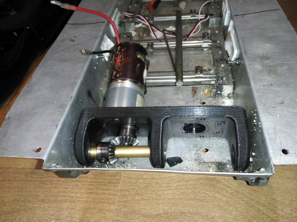
To the build:First trial of the setup on 3s. It's so good when things work at first try. Unfortunately, the gearbox was too fast(33:1) and ordered a slower one. The only bad thing was that the bores on the gears were a bit off center, that's why it sounds that way
Now with the 56:1:
-
1
-
-
M548
in General RC
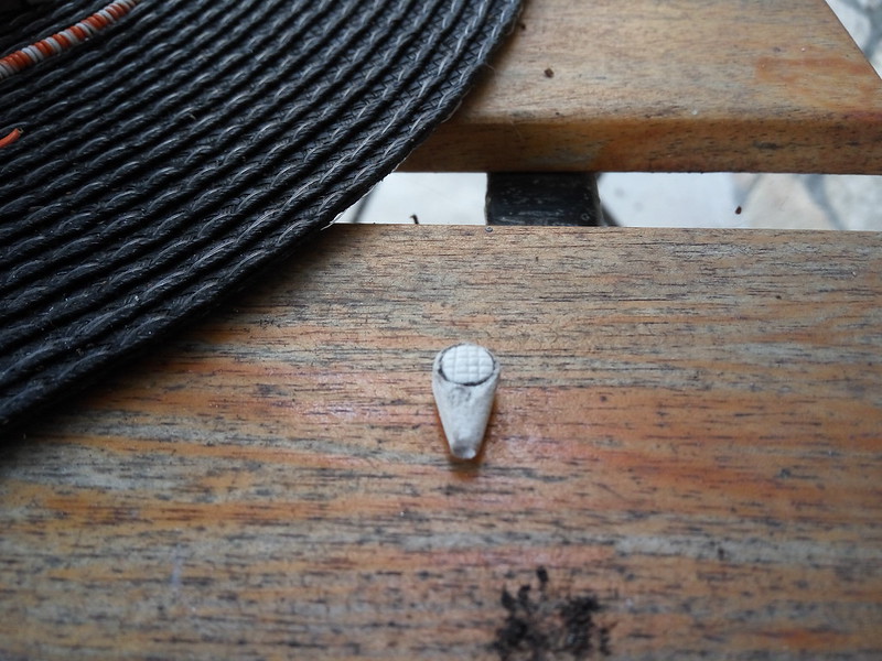
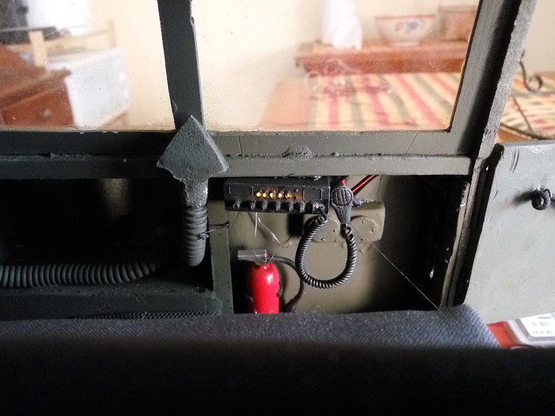
A while ago,a friend gave me a scale CB radio from Shapeways for my Unimog. The thing is that I never mounted it and it sat for a while in the shelf. But the M548 it's also perfect for it. So, I've finished it.
The radio was painted black, including inside with nail laquer for the light don't bleed out
Need the mic so I did a quick one on PVC, the round part was achieved pressing a bearing against the pvc. The rest was dremel and sanding
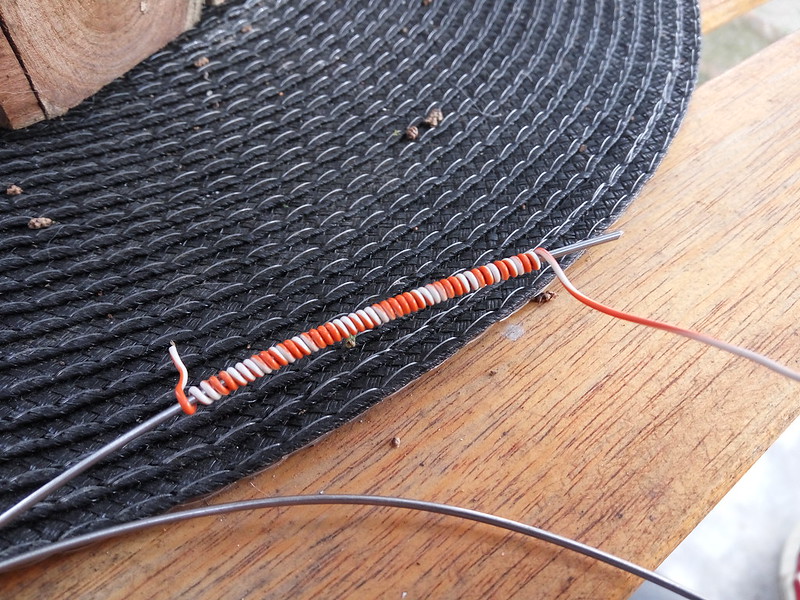
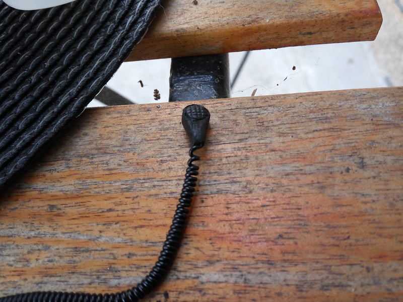
Some thin cable wrapped around a wire could make a scale spiral cable?
I think so:
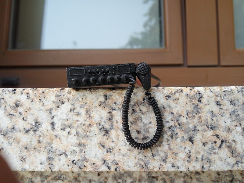
All assembled:So, there's a LED behind and drilled 1mm holes on the front for the light pass through. In place:
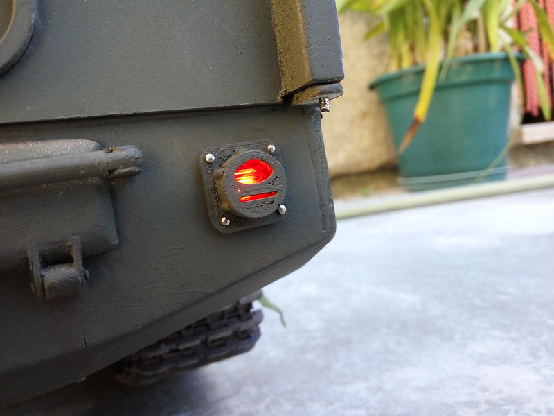
These LEDs were a PITA to mount. When I did the rear section,didn't thought in practicability to mount lights. But was doable:
Is a printed taillight with a real piece of stoplight inside 🙂
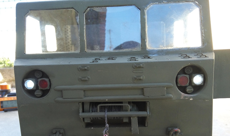
Headlights and winch:-
1
-
-
M548
in General RC
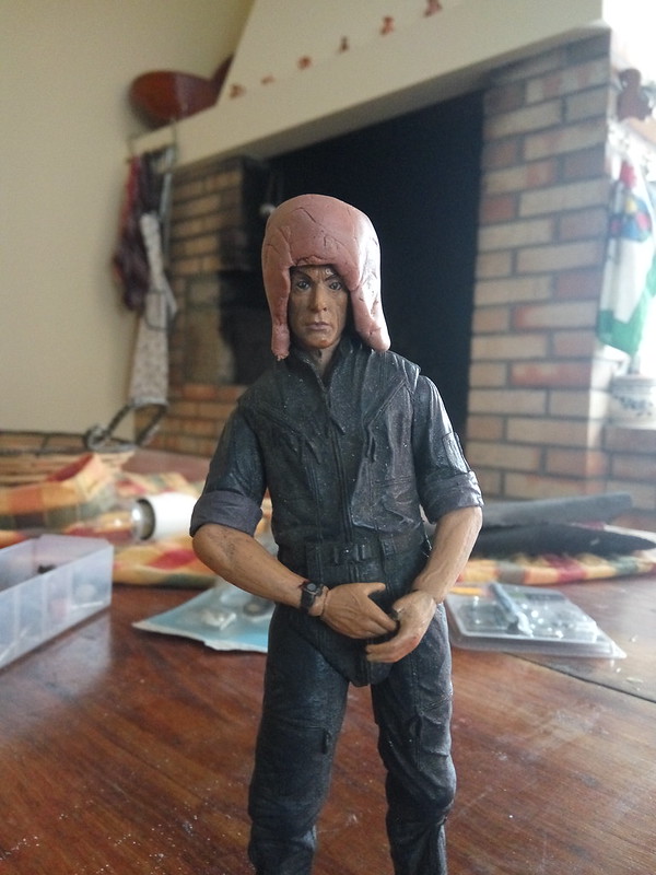
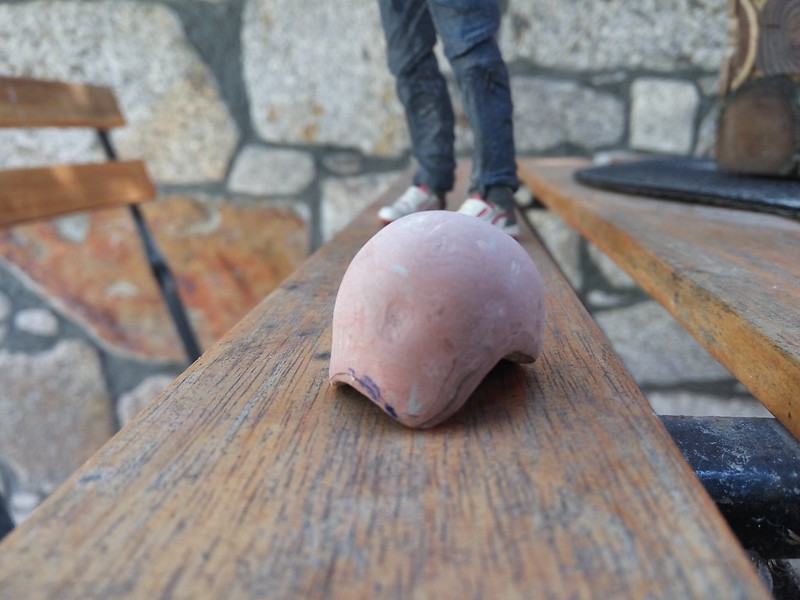
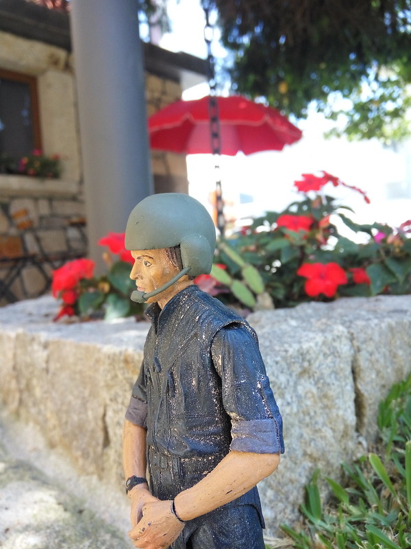
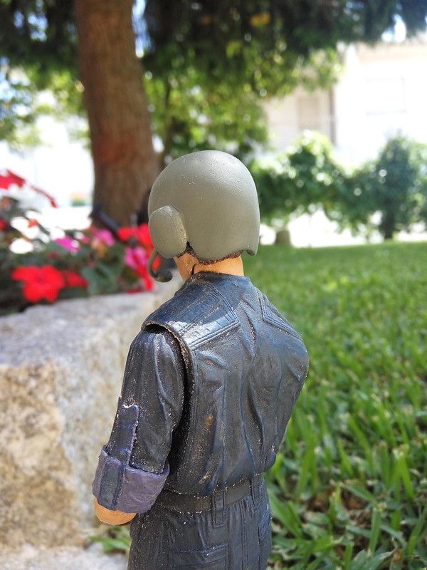
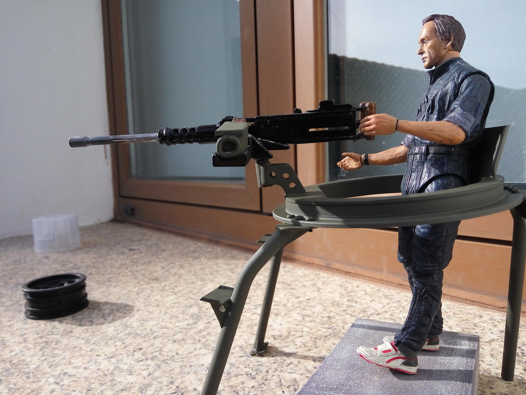
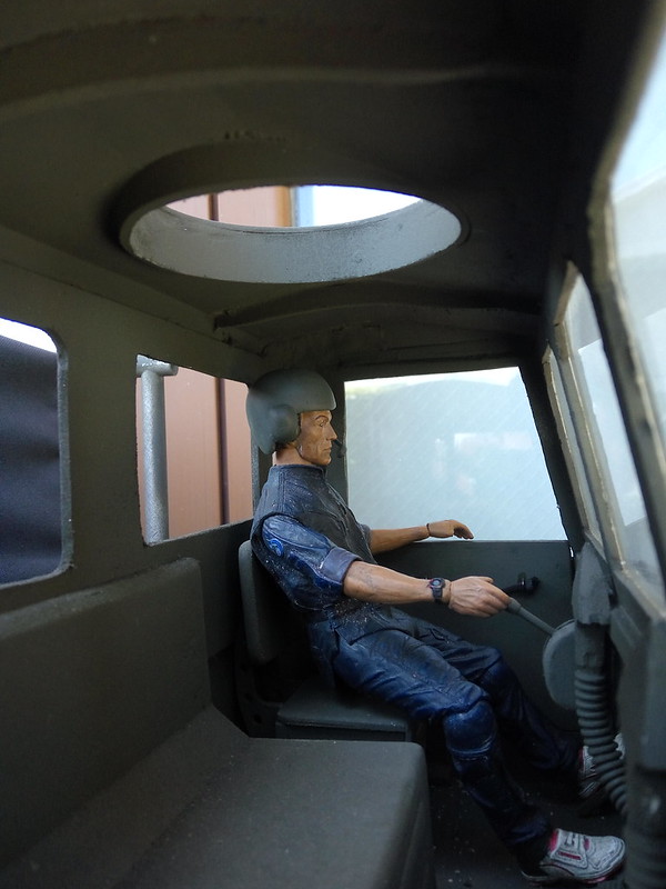
This is a bit odd at first but it gets better: An operator helmet for Bishop
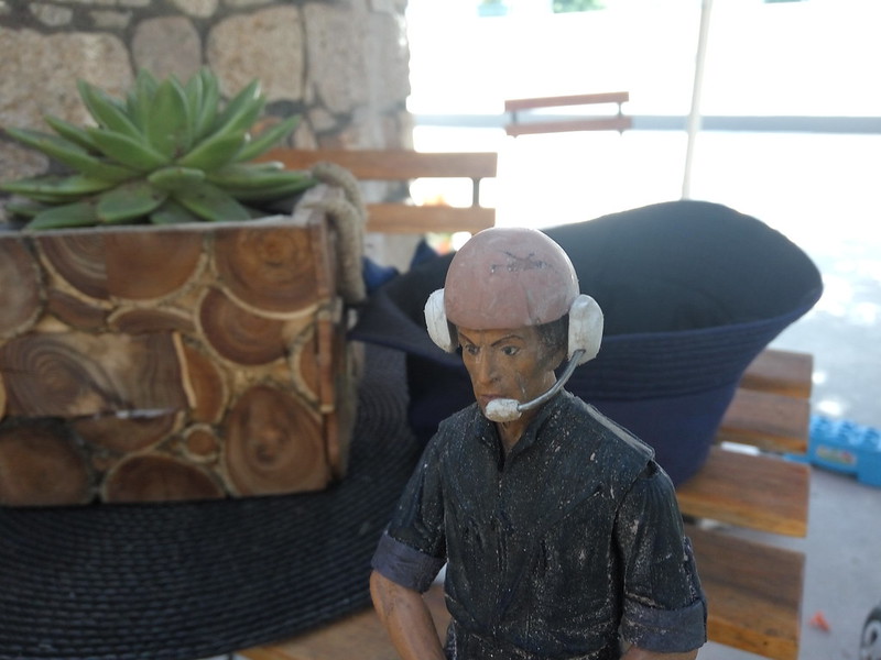
Put the epoxy putty on his head to do the rough shape:Closer to the final shape:
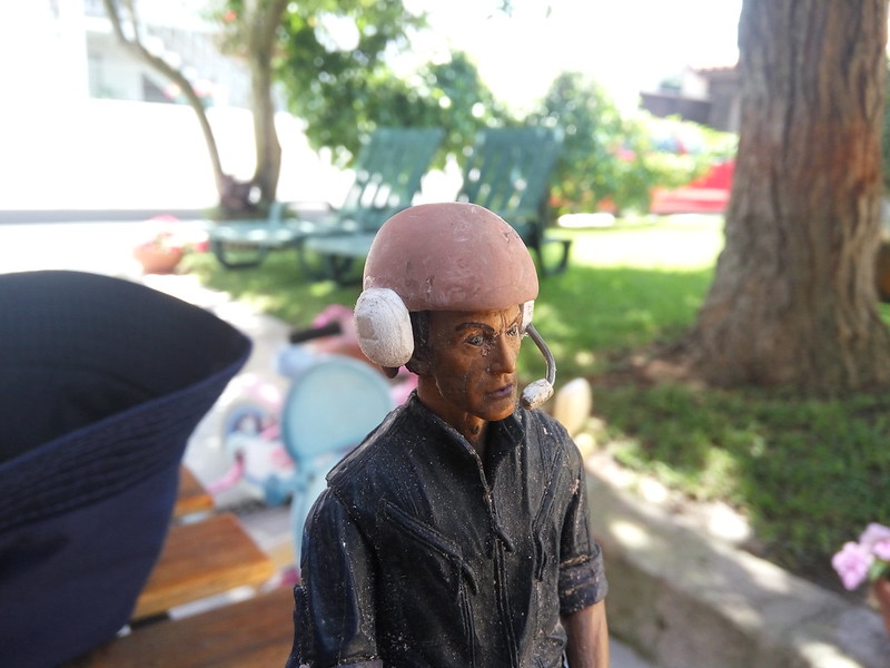
Ear pieces and mic:
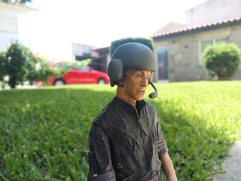
Painted:https://farm2.staticflickr.com/1764/29582315648_690682a541_c.jpg
-
1
-
-
M548
in General RC
Done something regarding to movement: I was limited to only one of my radios because of the mixing needed to make the truck move. But I also need that radio for the JK so instead of buying another receiver I risked it for a solution 10 times cheaper:Ordered an Hobbywing V-tail mixer.
Should have done this right in the befogging . Simply connect the plugs in the right positions and it's ready. The crappy weather that day only allowed indoor testing but responds well and didn't fail
And this is being silly on sand leftovers from house renovation s. It's running on 3s:-
1
-
-
M548
in General RC
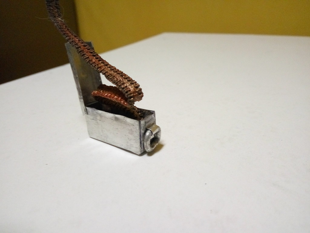
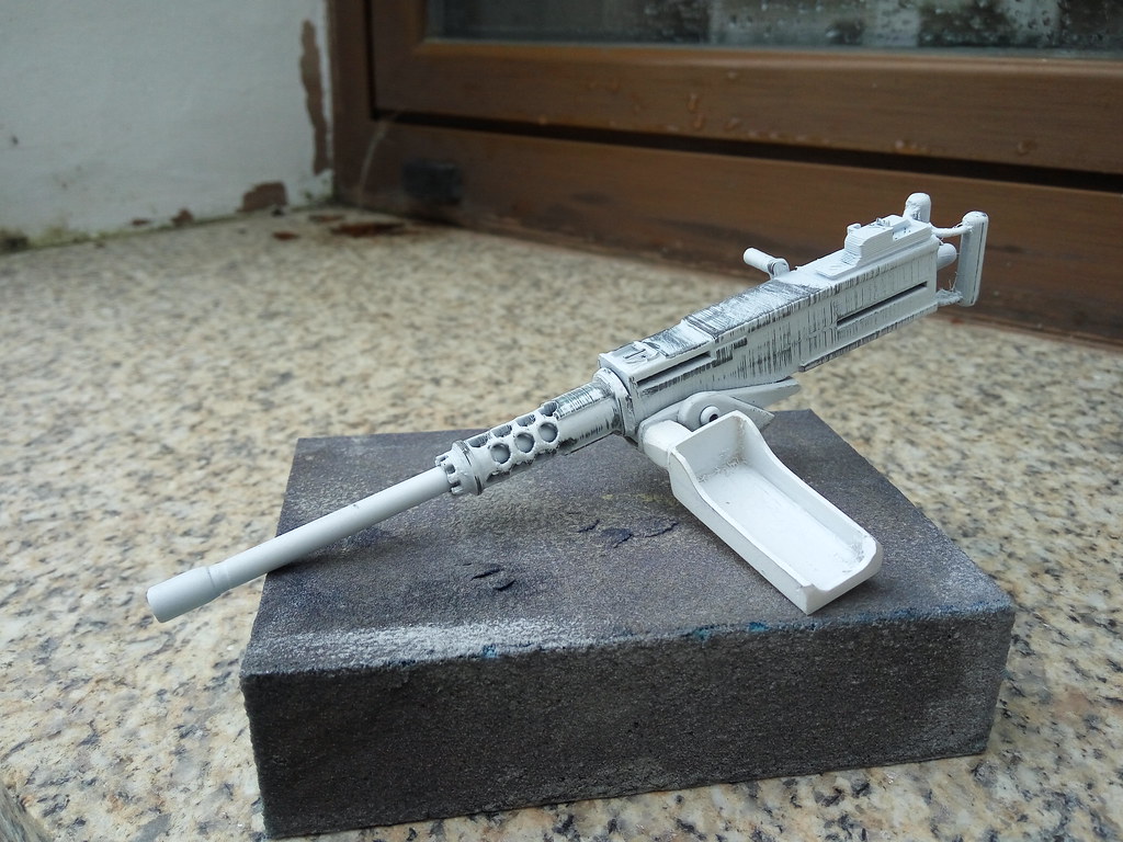
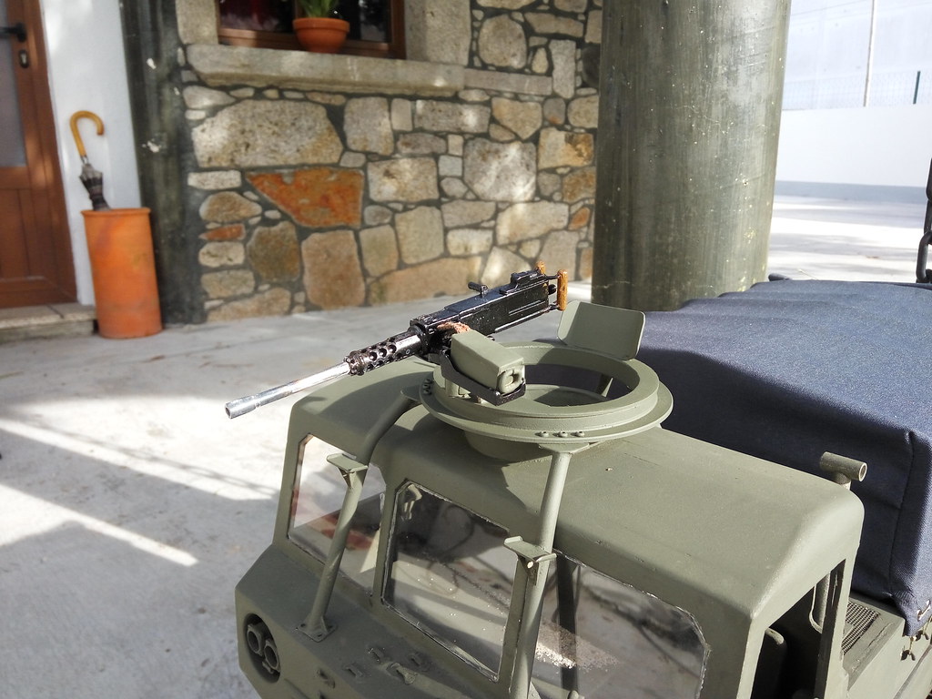
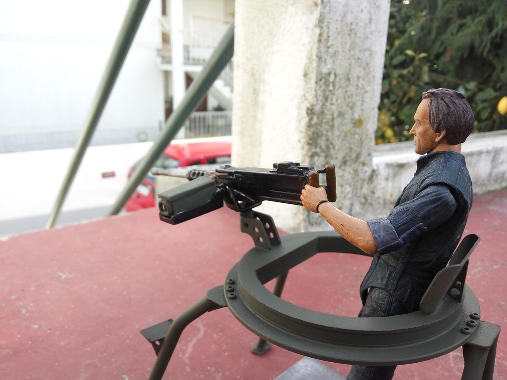
Some work on the M2 and it's mount:
The ring rotates, the gun pivots to the sides and up/down and it could be lifted to take out
The 3d model was supplied by a fellow Spaniard that's doing a fully printed M548. Added just the ammo box cradle, ammo box and the interface to the ring:
And the paint:-
1
-
-
I have these fake hubs I've ordered for the Unimog but found their way to the LC70. They are pretty nice for the price but they need something extra. Thought of adding the Toyota logo but not sure how. Too small for 3D printing and vinyl sticker. But a buddy of mine has a laser engraver. He liked the idea and helped with this:
-
3
-
-
M548
in General RC
I couldn't wait to test it. Here's a quick and crude edit from that day. We're still learning how to drive it and see it's limits. Tried some soft climbs. Tracks slipped out twice but doesn't stuck like the first attempts.
Hope you like it!
-
1
-
-
Very cool RC!
-
M548
in General RC
The real M548 uses shocks on their first wheel, each side (and the last,also) so I've circumvent the problem of not being able to do torsion bars for those wheels with an axle arm similar to the others but mounted on a flange with 2 bearings and a shock. The shock it's an axial one, gone from 93mm to 62mm,53mm compressed and 71mm extended. Shorter shaft and a "sleeve" to look more scale.
And that allowed for the first drive:
-
With this bumper assembled, could do the printed headlights and the lenses are bits of protection glasses (because they are curved pieces of clear plastic and not flat)
-
1
-
-
Update on the mats:
They have arrived yesterday, just sprayed a bit of black to see how they looked
-
1
-
-
M548
in General RC
Better look at the system with the spring steel bars
To try to make more clear, the round rods are the suspension arms' pivots . They are offset from side to side but the real one is too 🙂 . Those pieces with the grub screws allow to tune the ride height and the stiffness of the suspension
And this 2 videos of the suspension working
Only 4 wheels each side. The 5th wheels work on a different system
And my take on the tension wheel:
Not complicated as the real system but it works. Is basically a arm, rotating on 2 bearings and a shock with a spring inside to push the wheel against the tracks-
2
-
-
M548
in General RC
Do you guys know when we hit a bump in the project and affects the motivation?
I struggled with the suspension, discarded the 1st idea, the 2nd with torsion springs looked good but because i couldn't get cheap springs, decided to went "full builder" on this and try to copy the system on the 1:1: torsion bars.
This is the first prototype :
Video:
The tension can be tuned. First, by the wire diameter. It's spring steel, started with 2mm and now changed to 1.5mm. Then,moving the piece that connects the spring to the axle, changes the stiffness. Another advantage it's that the ride height is set and locked with a screw. In the ride height, the positive and negative travel it's the same
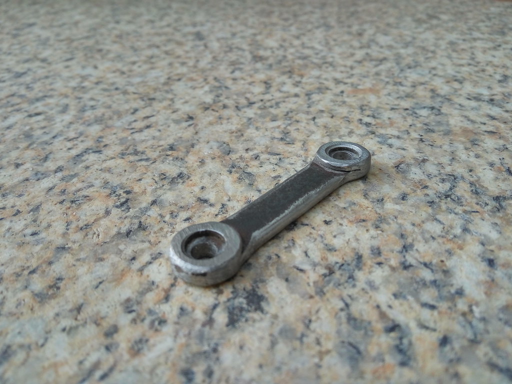
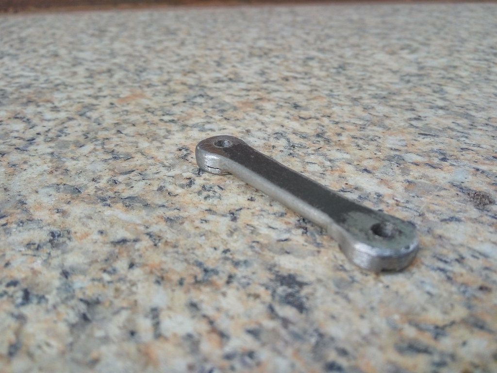
Suspension arms. The are steel bar with one washer welded at each end to add that 3d look and help to round the ends. Machined a bit on the center to make it thinner. Then, filed all the edges to look a cast piece. On the holes at the ends, will be a axle for the wheel and on the other, the suspension pivot
In the end, they'll be almost invisible. Half-hidden by the wheels and the tracks
And now,the "bones" of the suspension system :First, the blocks that will be bolted to the chassis and will hold everything
In place:
The arms are attached to 4mm steel rods that offset from each side like the real one. On the 1:1, the arms are connected to torsion bars. I opted to this system instead because is more adjustable. The photos show spring wire but I've replaced for 4x2mm spring steel bar.-
2
-
-
M548
in General RC
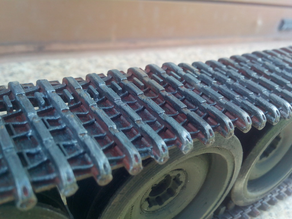
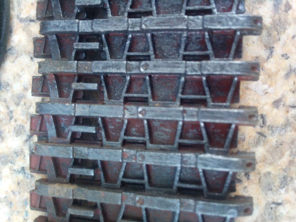
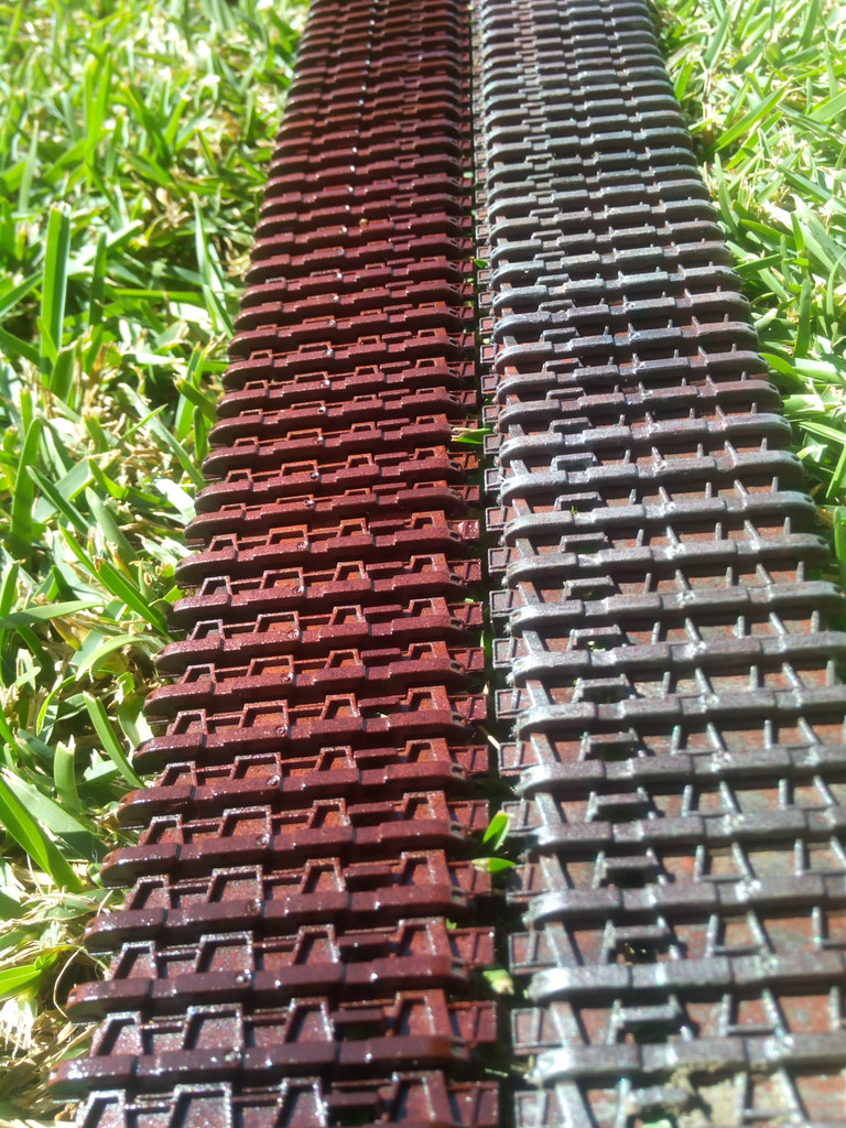
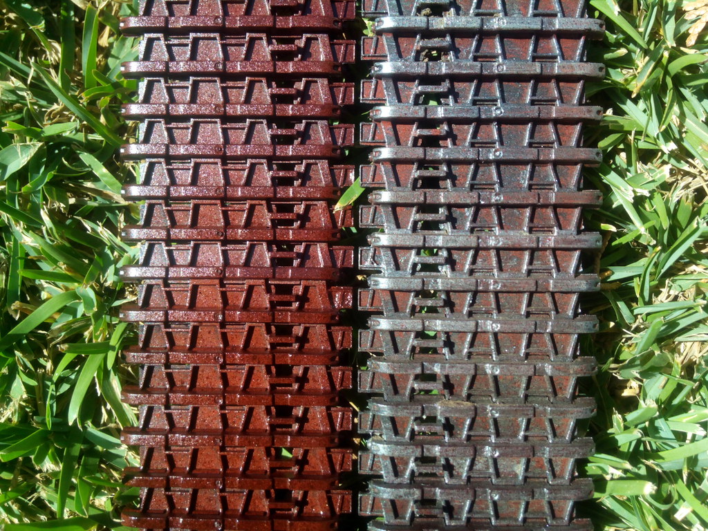
The tracks: In stock form , look too clean and being all black,don't seem scale. So i tried to weather them to look metallic and worn
This is the first one, used a rust red, and 2 different grays
because the red was too "red" for rust, on the second track applied a bit of dark brown and seems better
Stock and weathered:For those who are wondering if the color will hold, against the ground? sections that are in contact with the ground lost the paint but the black plastic turned to a dull gray
-
3
-
-
Machinist on a small company. mainly auto repairs
-
18 hours ago, Kpowell911 said:
Wow! The attention to detail here is mind blowing!
16 hours ago, Stormbringer said:yeh he really is doing scale models
Thanks!
Let's see if I don't get too ambitious like Icarus 🙂
-
1
-
 1
1
-


fotosevdeosdoInstagram.png.72541bb203d46df2526e10b09b3b9e0d.png)


fotosevdeosdoInstagram.png.0bc500cae4b0dfa9c6019592040c2b8b.png)


What did you do to your model today?
in General RC
Posted
Finally got the chance to trail a bit with 2 buddies. We really needed the therapy
1 Capo Sixer + Rochobby Willys 1/6 + my JK