Popular Post Nitroholic Posted August 5, 2021 Popular Post Share Posted August 5, 2021 and you think...hmmm...that might work. Was tidying my stock of Hyper parts up, seperating and putting together complete assemblies just to see what I had after I got everything unpacked following a recent house move. Shocks, wheels, a load of parts... I also had my brushless converted one out on the table as I was thinking about a rework of it's component layout. Was looking at the bits all together, comparing the steering setups..... when I also found this....which I had put together a little while back. It's made up from 2 spare Hyper 7 diff cases, with the mating surfaces cleaned up, and a slice out for a shock tower. Basically...it's a pass through diff for a 6 wheel drive setup. I plan to make a tube to replace the driveshaft cups to link the pinions together... Now I want to build this.... I mean...everyone should have a 6 weheel drive 4 wheel steer buggy.... right? 8 3 1 Quote Link to comment Share on other sites More sharing options...
AnthonyM Posted August 5, 2021 Share Posted August 5, 2021 Do it! I mean i duno how practical it will be but YOLO be fun to see 1 Quote Link to comment Share on other sites More sharing options...
BigGinge Posted August 5, 2021 Share Posted August 5, 2021 I think it would be rude not to now that we've seen this. Quote Link to comment Share on other sites More sharing options...
Shergar Posted August 5, 2021 Share Posted August 5, 2021 It would look great with a Tyrell 6 wheel drive paint scheme too! Quote Link to comment Share on other sites More sharing options...
Stormbringer Posted August 5, 2021 Share Posted August 5, 2021 Hmmmmm very interesting Quote Link to comment Share on other sites More sharing options...
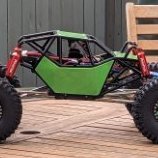
Popular Post BigGinge Posted August 5, 2021 Popular Post Share Posted August 5, 2021 Also… 2 4 Quote Link to comment Share on other sites More sharing options...
Stormbringer Posted August 5, 2021 Share Posted August 5, 2021 3 minutes ago, BigGinge said: Also… yeh was thinking of that as well lol Quote Link to comment Share on other sites More sharing options...
Hell horn. Posted August 5, 2021 Share Posted August 5, 2021 The 6 wheel police tank from carmagedon. Do it. Would look amazing. Basically this. 2 Quote Link to comment Share on other sites More sharing options...
Popular Post Nitroholic Posted August 5, 2021 Author Popular Post Share Posted August 5, 2021 well..... it could certainly be an interesting project. Currently looking at how I could re-arrange the internal components to shorten the back part of the chassis. Going to make a mockup chassis and see how it would all fit. Not a clue what I would do with regard to a bodyshell, but I have a few ideas to play around with. Will see what's what.... but if I can get the thing shorter so it's no more than 30mm longer than a stock Hyper....it should go well too. I also figured if I mount the steering arms in 2 different points on the servo arm...I could get proportionally different steering...with the outer wheels moving further than the second pair. This will make it turn more than crab I am putting far too much thought into this 🙂 2 2 Quote Link to comment Share on other sites More sharing options...
Stormbringer Posted August 5, 2021 Share Posted August 5, 2021 why not mate it does seem an interesting project 1 Quote Link to comment Share on other sites More sharing options...
Popular Post Nitroholic Posted August 6, 2021 Author Popular Post Share Posted August 6, 2021 Well...that went surprisingly well! Grabbed a bit of thin MDF strip ( was packing from some self assembly furniture, but it always comes in handy!) and started roughing out hte layout. The front setup is fine, and the MDF thin enough to bend to the shape hte front kickup would have. The second setup will need a custom top brace, as the steering posts are too far away. It was pretty clear that the path for a front steering linkage was through the front shock towers, and a little kink in some M4 studding made me what I needed. It alctually seems to work. I f I get flex issues, then I will take the time to 3D print a centre piece to take a copuple of rod ends. That wont flex, but I reckon the rod will work well enough. In testing...it works as long as I hold the back steering posts steady. I will need, as I mentioned, a custom upper brace for the rear steering block, and a brace between the 2 front diff housings. Both will be simple sheet ally and easy to make. Then I looked to the rest. I pulled hte centre diff form the donor buggy, with motor attached. Putting it in place, along with the shortest driveshaft I had in the box of odds and ends, I worked out how far I could shorten things over stock. Ditching the stock chassis brace, and fabricating one that runs over the top to the centre diff solves many issues, and allows the motor to sit fairly close to the rear assembly. The steering servo will go pretty much in the stock location....and I can sit the ESC up above the centre diff on the new rear top brace. Battery trays...I could go with the one I already made....or....as a preference....I want to have 2 'pannier' trays. I run it on 4S using 2 2s....so that would give me a balance. A job for the 3D printer. So...what does it look like now? I will put a couple of spacers under the centre diff mounts, so I don;t have a 'slot' hole for the centre diff to let the muck in. Compared to a stock Hyper 7.....the front wheels would site pretty much dead centre of the 2 front wheel sets, so the thing is only about 30mm longer than a stocker. 6 Quote Link to comment Share on other sites More sharing options...
Hell horn. Posted August 6, 2021 Share Posted August 6, 2021 Very cool. When the wheels turn do they hit anything. Looks very close. Can't wait to see what you do with this build 1 Quote Link to comment Share on other sites More sharing options...
Nitroholic Posted August 6, 2021 Author Share Posted August 6, 2021 no...they don;t hit. they are close...and I might ease it back a fraction to give room for tyre growth at speed. Turning is fine, as the wheels turn together, and stay well clear. plenty of adjustment in the linkage I made, as its wound as far in as it goes. I could move the things about 10mm further apart if I need to. 1 Quote Link to comment Share on other sites More sharing options...
Hell horn. Posted August 6, 2021 Share Posted August 6, 2021 Cool cool. Should make a fun car. Quote Link to comment Share on other sites More sharing options...
Stormbringer Posted August 6, 2021 Share Posted August 6, 2021 Wow mate thats gonna look incredible Quote Link to comment Share on other sites More sharing options...
walkbythesea Posted August 6, 2021 Share Posted August 6, 2021 Following this with great interest 🤘😎 Quote Link to comment Share on other sites More sharing options...
Nitroholic Posted August 6, 2021 Author Share Posted August 6, 2021 Gotta go out of town for a couple of days.....but while I'm away.... I will be sketching out the battery tray designs I want to try, looking at 3D printing a servo mount, and a few other bits asnd pieces I would like to add. 1 Quote Link to comment Share on other sites More sharing options...
Shergar Posted August 6, 2021 Share Posted August 6, 2021 With half a wood chassis I bet it wooden half go 😉 1 1 Quote Link to comment Share on other sites More sharing options...
Nitroholic Posted August 14, 2021 Author Share Posted August 14, 2021 OK.....time to get serious with this. Having done the rough mockup with the timber chassis, I could see how most of this would work and how the functional part of drive and steering cuold be arranged. There was only one bit I needed to sort out, and that was a driveshaft. My original thoughts around a 6WD truck had used 4 wheels at the rear, not the front. I intended to remove both the drive cups from the diffs between the 2 rear axles and link it by simply drilling an 8mm hole down the centre of a bolt, and hooking it up with 2 grub screws. Simple....and as it uses the same principle as the stock drive cups to hold, I had no concerns over how it would hold up. But....there is a problem at the front. The first pair of wheels need to be on an angle for the kickup. This is a serious thing, as it allows the suspension to absorb the bumps as it hits lumps at speed. Were it vertical, the impact would be taken by the suspension pivots....and not the springs. So...the kickup had to be there for the first pair. The second pair don;t need to be angled...but it means the coupling CANNOT be parallel, and has to be at an angle both sides. That meant a driveshaft.....of some sort. So..... A bolt was founf with an outside diameter roughly that of the end of a stock driveshaft. 2 3mm holes were drilled across it. To make sure they were as centred as I could get them, I had to file a couple of small flats to get an accurate centre punch divot so the drill didn't wander. It's not going to be 100% perfect....but its as close as I can get it. I then had to cut the bolt to length, and drill a further 2 holes in the ends ready to be tapped out to take an M4 grub screw. Effort one resulted in a snapped drill bit as the hole breached into the cross drilling. Could not remove the stuck drill tip....so that went in the bin. As I hate wastage......guess what is being used to provide the driveshaft pins..... yup....shank of a 3mm drill bit 🙂 The ends were both drilled and tapped to take an M4 grub screew, and the pins chopped to size with the Dremel cutting disc. It's very hard steel......so forget hacksawing it! The bolt might need a little thinning where the thing exits the cups, but I won;t if I don;t have to. I reckon I have enough free motion to have it clear without rubbing. It will be fitted with a couple of o-rings either end to ensure no rattling, but the thing looks like it will server the required function. Both grubscrews have been locktited in place, and the ends made as neat as I could. For size comparison....that is a short centre driveshaft from a Hyper 7 ..... My mini-driveshaft is around 30mm pin to pin. It will place the wheels about 10mm apart at the front, but also give me scope to adjut that if I feel I need to. Not by much....but...enough! Now I can go ahead and make the chassis plate without worrying if the thing is going to be a bust....as there are no other issues I can see that will be a major problem. Plan B for the driveshaft involved welding up an old driveshaft into a sleeve after cutting the heads off. Might still make a 'B-shaft' later on to see if it works better. Will need to find a bolt....drill a hole down the bore..... and weld the ends up. Then clean it all up 3 Quote Link to comment Share on other sites More sharing options...
Shergar Posted August 14, 2021 Share Posted August 14, 2021 I can’t wait to see this in the flesh/video (!) flat out on a fast turn 👍 Quote Link to comment Share on other sites More sharing options...
Nitroholic Posted August 14, 2021 Author Share Posted August 14, 2021 Plan B implemented anyway....just becuase I wanted to see if it worked well enough! Took an old driveshaft, which actually was bent anyway, but not where it mattered for my purposes. Both ends were cut off...but at an angle....not flat. Bit of filing was needed to get them the same ....but not a problem. Then I found a bit of 8mm steel tube, just the right size for my needs. A piece was cut to length, then a slot cut out of one side. Both bits of driveshaft were tapped into the sleeve, lined up on the slants, and clamped up to keep the pins parallel. Then I welded the centre slantsthough the slot....and welded all the way up the slot. This should ensure the centre part of the shafts got welded together, and both shafts are then welded to the sleeve. I wanted a strong join. Then I could grind back the excess, and leave basically an 8mm sleeve attached around the join and supporting it. I didn;t want to over-grind the weld...but I wanted to at least try and balance the thing a bit. Seems to have worked pretty well. Bit more fine fettling needed....but as the join was lined up on the pins....I got good weld all along. Going to get some wet and dry on it, and if I can hold it in the drill chuck...spin it up and get it shiny. Have both options to fit and test run when its all done 3 Quote Link to comment Share on other sites More sharing options...
Hell horn. Posted August 14, 2021 Share Posted August 14, 2021 The proline Pro Mt 4x4 uses a super short link for front wheel drive so that might work well for your build. Worth a try I think 1 Quote Link to comment Share on other sites More sharing options...
Nitroholic Posted August 14, 2021 Author Share Posted August 14, 2021 Anyone know how long that actually is? Annoyingly, they are only sold as pairs with the long rear shaft I don;t want..... and stock seems pretty scarce. Amain have some....but at a price ( with tax and postage) 1 Quote Link to comment Share on other sites More sharing options...
Kpowell911 Posted August 15, 2021 Share Posted August 15, 2021 (edited) I seem to remember my Tekno EB48 having a very small centre shaft? https://www.ebay.co.uk/itm/TKR8000-TEKNO-RC-EB48-4-1-8-BUGGY-FRONT-REAR-CENTER-DRIVE-SHAFT-AXLE-BONES-/284404664105?mkcid=16&mkevt=1&_trksid=p2349624.m46890.l6249&mkrid=710-127635-2958-0 Edited August 15, 2021 by Kpowell911 Quote Link to comment Share on other sites More sharing options...
Popular Post Nitroholic Posted August 15, 2021 Author Popular Post Share Posted August 15, 2021 Decided to get stuck into the chassis today. Had a piece of suitable alloy hanging around from a previous project ..... so that was located in the dim recesses where I stash all the stuff normal folks throw away. Permanent markers make great replacements for proper marking blue, and after much measuring, scribing of lines, centre punching and triple checking....I had the front section marked out. It's really important to make sure you have all the locating holes and the mounting holes correct. Get it wrong, and the holes either wont line up...or the diff will sit crooked. Don;t want either! as you can see here...the top two lines were a little off and had to be redone...but if you don;t check...while the error may be tiny at the front...by the time you get to the second diff its noticable. Easy to correct here...not so easy when you drill! As a double check, I screw a block to the back so I can mount it up on my bench drill. That way...I can drill a series of holes and use the adjustable vice on it to move it along one axis to drill the next hole. Then I know its good. With the holes drilled and cleaned up, I could cut out the chassis shape. I copied the front section exactly, then blended the second set of curves in so I had the same shape where it mattered. I cut and filed one side...then made a template in thin card to duplicate the shape on the other side. The exact shape isn;t vital...but having both sides the same is! I gave it a clean up and a brush over with a scouring pad. I am not a fan of 'polished' alloy as a final finish...but this gives a nice smooth look. The underside has the protective film on it to avoid scratches. The top still needs a little work to remove the marking out, but I don;t mind that so much. The front end was bent to replicate the kickup on a stock chassis. The only bit I am not 100% happy with is the front square cutout. It's a little off and larger than it needed to be. But...I will just have to live with it. It will be hidden by the front bumper anyway. Last job was to test fit the front diffs and the driveshaft The front diff will need to be pulled apart and the internals flipped over. As it stands....the pass through diff inverts the rotation.....and this would mean the front pair of wheels spinning the wrong way. Hyper 7's have a symnetrical casing...so flipping it over is easy. Many folks have done it by accident....ending up with a car spinning it's wheels and going nowhere! The driveshaft copes with the kickup angle nicely and nothing binds. While the diff is apart it will get a clean and regrease. Seems daft not to service it. I normally run fronts on 7K .... but I might go a little lighter due to the layout. Grease in the housing and swap out any rough bearings. Will run a sway bar on the very front axle...see how that goes. Want to get the front all built up and the steering in before I start on the backend. Thats basically stock anyway 5 Quote Link to comment Share on other sites More sharing options...


Recommended Posts
Join the conversation
You can post now and register later. If you have an account, sign in now to post with your account.