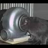
Fr0sty Posted May 3, 2010 Share Posted May 3, 2010 (edited) http://www.youtube.c...h?v=AfGMvmXz0OY Needs some work to dial it in but i have it running. Let me know what you think PS: This cost me £25 to build the next cheapest option i can find is $1550.00 USD* I also have very limited skills when it comes to building things so i really would say just about anyone could make this them selfs Edited May 3, 2010 by Fr0sty 2 Quote Link to comment Share on other sites More sharing options...
Sphinx Posted May 3, 2010 Share Posted May 3, 2010 Thats brilliant, did you make that you're self? Gav Quote Link to comment Share on other sites More sharing options...
Fr0sty Posted May 3, 2010 Author Share Posted May 3, 2010 Thats brilliant, did you make that you're self? Gav Yes i built the rolling road from some MDF, Drainpipe, Thread Bar (Not my first choice i just couldn't find suitable axles) and some Some Bearings. The electronics are basically a magnet on the roller (Magnetix Peice thats the blue bit on the roller) and a coil (Under the ducktape) which i had to make my self from some magnet wire and a small bolt. Solder the ends of the coil to an old set of headphones and plug it into the line in (MIC) port of your computer. The software was written by RCDAMO and can be downloaded here SimpleDyno Very simple idea but it works great. I also made it big enough to fit my 1/8th truggys on makes tuning the engine a lot simpler when its not doing 40mph round a field lol This is just the first build for now i intend to add some fans to the base and a better way of holding the cars in place. Quote Link to comment Share on other sites More sharing options...
cerbrus2 Posted May 3, 2010 Share Posted May 3, 2010 Dyno software is nice and easy, but any more information on how to build the coil, magnets etc? Quote Link to comment Share on other sites More sharing options...
Fr0sty Posted May 3, 2010 Author Share Posted May 3, 2010 Dyno software is nice and easy, but any more information on how to build the coil, magnets etc? I am trying to write a basic guide now should be ready in an hour or so Quote Link to comment Share on other sites More sharing options...
Dieseldog Posted May 3, 2010 Share Posted May 3, 2010 Thats pretty good, you could make some money out of that if you made it a bit better, not saying its not lol Quote Link to comment Share on other sites More sharing options...
adolf hamster Posted May 3, 2010 Share Posted May 3, 2010 that looks pretty good, ive never been interested in how my engines perform, always preferred to go by 'dam thats fast' or 'not enough power there' but i'm a sucker for diy might try this just for the sake of it Quote Link to comment Share on other sites More sharing options...
cerbrus2 Posted May 3, 2010 Share Posted May 3, 2010 that looks pretty good, ive never been interested in how my engines perform, always preferred to go by 'dam thats fast' or 'not enough power there' but i'm a sucker for diy might try this just for the sake of it Exactly. And my misses will be extreamly pleased with the 5th scale dino sat on the front room floor, can the software do 4wd? Quote Link to comment Share on other sites More sharing options...
KieranBolton Posted May 3, 2010 Share Posted May 3, 2010 Maybe iff you had a splitter on the mic's ? kieran Quote Link to comment Share on other sites More sharing options...
Fr0sty Posted May 3, 2010 Author Share Posted May 3, 2010 (edited) Build your own RC Car Dyno for under £30 This is only a basic guide to how i did it and will be updated over time. First of all i used a sheet of 10 mm thick MDF and some cabinet brackets to make a basic box The rollers i made from some ABS drain pipe i had laying around (I use it to make ABS tyres for a bit of drift fun) The end caps where a little trickier to find and i wish i kept the receipt to give a product code but basically there from B&Q in the plumbing section and are a perfect fit for the end of the drainpipe. I drilled a hole to take the bushings i had lying around in the end caps. To get them to fit nice and tight i placed the end cap in boiling water and the bushings in the freezer for a little bit them popped them in, When the temperatures settled they sat in nice and tight (Its essential to get them dead center or the rollers will vibrate like hell) I then cut the thread bar to size and placed it through the newley made roller Rinse and repeat for the other roller so you have 2 Cut your "MDF Box" to fit your rollers in, I left one roller with a big gap so i can later add some adjustment to the width of the rollers when needed. Use thread-lock nuts to fasten the rollers to the box (Or they will just spin right off as i found out) You should now have a basic rolling road and its a good time to test the balance of the rollers etc, Go on you know you want to get your car on there Ok now to the electronics You will need a small magnet, a coil, a set of old headphones and a soldering iron. First of all you can get a small magnet from the earpeirce of the headphones your about to cut up, And you can make a coil your self if you don't have one. Cut one end off the headphones and open the earpeice inside there should be a small coil and a small magnet, Remove the magnet and throw away the rest. Unfortunately the coil from the earpeice isnt strong enough (I tried) so your going to have to find one or go scrapheap challenge on its @ss to find the bits you need. Luckily the magnet wire is fairly easy to find its inside most power supply's (WARNING THIS CAN BE VERY DANGEROUS RISK OF ELECTRIC SHOCK IF YOU DON'T KNOW WHAT YOUR DOING) or old radios. The stuff i used is about 30Awg thickness it looks like bare copper wire but its varnished You now need a small bolt or nail (I used a 8mm long bolt) wind the magnet wire around the bolt as neatly and tightly as you can from one end to the other then back again then back again (So you have 3 layers) i used a drill to make this easier hold the bolt in the drill then wind the wire on slowly using the drill. leave 2 tails of wire about 2" in length to solder the headphone wire to. Ok now take the end of the headphone wire you cut the earpeice off and clean the ends of the 2 wires ready to solder to the 2 tails of wire on the coil. Next attach the magnet to your roller near the edge but make sure it spins freely and fix the coil on the side of the box so it lines up with the magnet but does not touch i have about a 5mm gap. Download the SimpleDyno software and plug the end of the headphone into the line in port of your PC. Setup the size of the rollers, wheels etc in the software fix your car down (Im still trying to solve this) and dyno that baby Enjoy and please post your feedback to help improve this idea Credit to RCDAMO1 for the original idea and writing the software. Edited May 3, 2010 by Fr0sty Quote Link to comment Share on other sites More sharing options...
Sphinx Posted May 3, 2010 Share Posted May 3, 2010 (edited) Use thread-lock nuts to fasten the rollers to the box (Or they will just spin right off as i found out) Remember guys who is the cheapest Gav Edited May 3, 2010 by JamesChatz Please don't quote all the pictures. Quote Link to comment Share on other sites More sharing options...
owling2005 Posted May 3, 2010 Share Posted May 3, 2010 (edited) ok i get the concept of this i worked a fair amount of magents and transformers what i wanna know it how you link it to head phones do u link the enamled wire in the headphones to one of the the coils ? the bolt as i think its meant to be from this badley drawn rougth template maybe 1 of the 2 of you will be able to shed some light PS i can draw this bigger if need be if what i think is true then u chould use the other headphone for the 2nd roller then ... geek at heart BTW UK people 30 AWG enamaled wire Edited May 4, 2010 by owling2005 Quote Link to comment Share on other sites More sharing options...
Fr0sty Posted May 3, 2010 Author Share Posted May 3, 2010 (edited) ok i get the concept of this i worked a fair amount of magents and transformers what i wanna know it how you link it to head phones do u link the enamled wire in the headphones to one of the the coils ? from this badley drawn rougth template maybe 1 of the 2 of you will be able to shed some light PS i can draw this bigger if need be if what i think is true then u chould use the other headphone for the 2nd roller then ... geek at heart Ok ill try to explain. First they are stereo headphones so each earpeice has 2 wires (except in some cases where they share a ground) i have only used one earpeice (2 wires) one wire to each side of the coil. ()()()()() | ------ | | ------ | | ------ | | ------ | Wire1 Wire2 LOL diagram in asci Because you can use stereo (2 channel) input on the line-in it is possible to do 4WD however the SimpleDyno software does not support that yet The basics of how it works are whenever you pass a magnet over a coil a small amount of electricity is produced when this is attached to the line in a detectable signal is produced each time the magnet passes the coil and the software is able to calculate RPMs from this Edited May 3, 2010 by Fr0sty Quote Link to comment Share on other sites More sharing options...
owling2005 Posted May 3, 2010 Share Posted May 3, 2010 so really ur running two coils ? 4 tails yes ? Quote Link to comment Share on other sites More sharing options...
ravenguard Posted May 3, 2010 Share Posted May 3, 2010 (edited) will it work on 4wd ? 2 wires per coil, wondering if the software will be updated for 4wd Edited May 3, 2010 by ravenguard Quote Link to comment Share on other sites More sharing options...
DamoRC Posted May 3, 2010 Share Posted May 3, 2010 Fr0sty, Nice work and I am really happy to see that software actually running on someone else's computer. There was a question on AWD / 4WD. I have a version right now than attempts to read 2 channels (which could be a front an rear roller sensor) but it is not working quite right yet. But you might not need it unless you think you are getting a lot of slip from one end or the other. One other word of advice - if you use the software, you are better off fitting the raw time and RPM data in Excel (or something like it)in order to calculate torque, power etc as the "live" values are pretty noisy. I would like to include the curve fitting in the software (and I am working on it) but it's not quite there yet. Good luck. DamoRC Quote Link to comment Share on other sites More sharing options...
Fr0sty Posted May 3, 2010 Author Share Posted May 3, 2010 will it work on 4wd ? 2 wires per coil, wondering if the software will be updated for 4wd I am only using 1 coil 2WD because that is all the software supports right now, the author does say he is working on 4WD (2 Coils) and it is technically possible so i dont see why not Quote Link to comment Share on other sites More sharing options...
Spoonmeister Posted May 3, 2010 Share Posted May 3, 2010 Will have to give this a go and see what it's like Should be able to do this otherwise the country's doomed as far as engineering goes BTW, I'm an engineering student Quote Link to comment Share on other sites More sharing options...
Fr0sty Posted May 3, 2010 Author Share Posted May 3, 2010 (edited) Hi Damo good to see you here The software is running fine in Windows 7 (run in administrator mode) and i am getting it set up nicely now with fairly accurate readings once you remove the noise from the log. I think this is a great addition to any local club and i am sure that between members skills most clubs should be able to build one and get a lot out of it Edited May 3, 2010 by Fr0sty Quote Link to comment Share on other sites More sharing options...
DamoRC Posted May 3, 2010 Share Posted May 3, 2010 Fr0sty - I would be interested in seeing some of the log files that you have generated - can you PM one or two to me? Quote Link to comment Share on other sites More sharing options...
Fr0sty Posted May 4, 2010 Author Share Posted May 4, 2010 Fr0sty - I would be interested in seeing some of the log files that you have generated - can you PM one or two to me? I will generate some fresh ones tonight and send them over, I will sample a few different cars to get a range Quote Link to comment Share on other sites More sharing options...
Fr0sty Posted May 6, 2010 Author Share Posted May 6, 2010 Here are the logs i have done 3 runs each of a Stock TT-01E and a Stock F103RS on NimH. Each run consists of Steady acceleration to full, Full acceleration, Full acceleration, Steady acceleration to full. with each being held at full for 2 seconds then all stop for 2 seconds. I did each run 3 times for each car. Hopefully this should give you some data from the software on a different dyno and with the cars being stock 540 they are easy checked against known outputs for the cars to see how accurate it is Enjoy Dyno Logs Quote Link to comment Share on other sites More sharing options...
-dash- Posted May 6, 2010 Share Posted May 6, 2010 Tecnicaly it allready does 4x4. the slip on the rollers is very very small if any. Providing the rollers are very very free spining (opened all my bearings got all grease out and put realy thin oil in them so thay spin for ages now there was way to much drag on them for nitro engine and would give false info like it was trying to spin up a higher mass roller) All you do for 4x4 is add both rollers mass into one. (eg) 1 roller = 300g put in 600g for total mass @ damo thanks for the coil pic youtube would not let me log in forgot my password so could not reply Ps gona try a reed switch as a pickup and see if that will lower pickup noise as it gives a very clear spike signal rather than a wave. just not sure on reed switch max rpm it can take. Quote Link to comment Share on other sites More sharing options...
Fr0sty Posted May 6, 2010 Author Share Posted May 6, 2010 (edited) Here is the data graphed and curved with different methods the results seem to compare to what i estimated the car to be at stock. This run was with smooth acceleration dash i would love to see a pic of your road be interesting to see how different people do it to find the best way to improve each others roads Edited May 6, 2010 by Fr0sty Quote Link to comment Share on other sites More sharing options...
-dash- Posted May 6, 2010 Share Posted May 6, 2010 Mine aint nothing flash nomal thing rip other things to bits to make new things. steel box section 4 big pillow block bearings 13mm shaft 120mm roller. bigest prob i had was getting end caps with hole 100% in middel. found easy way in end well ish. bit of mdf drill hole push the shaft thro so really tight then put shaft in bench drill turn it on with 40grit sanding block resting on the drill platform and sand it to fit. tada one perfect circle with hole in middel. there allways a cheap way of doing things hehe oh wait bigest pain is not having excel and i run nitro engines so need find cheap rubish laptop aint doing it in my house hehe. try rember to take pic when at work Quote Link to comment Share on other sites More sharing options...


Recommended Posts
Join the conversation
You can post now and register later. If you have an account, sign in now to post with your account.